Ray Tracing in One Weekend
译注: 本文为 Ray Tracing in One Weekend 一书的中文翻译,某些地方与原文不同,因为我希望在最大限度保持原义的同时使得文字更符合中文的语言习惯,如果有翻译错误,敬请在评论区指出 orz
原始内容: https://raytracing.github.io/books/RayTracingInOneWeekend.html
Output an Image 输出一个图像
PPM 图像格式
PPM (portable pixmap) 是一种无损压缩的图像格式,这是维基上的介绍:
创建图像版 "HelloWorld"
在 VSCode 中创建一个目录,包含如下文件
\build
CMakeLists.txt
rayTracing.cpp
在 rayTracing.cpp 中写入能输出一个图像的内容:
// rayTracing.cpp
#include <iostream>

int main() {

    // image

    int image_width = 256;
    int image_height = 256;

    // render

    std::cout << "P3\n" << image_width << ' ' << image_height << "\n255\n";

    for (int j = 0; j < image_height; ++j) {
        for (int i = 0; i < image_width; ++i) {
            auto r = double(i) / (image_width - 1);
            auto g = double(j) / (image_height - 1);
            auto b = 0;

            int ir = static_cast<int>(255.999 * r);
            int ig = static_cast<int>(255.999 * g);
            int ib = static_cast<int>(255.999 * b);

            std::cout << ir << ' ' << ig << ' ' << ib << '\n';
        }
    }
}
关于这个代码的一些注意事项:
- 按照惯例,每个 r/g/b 分量在内部都用实数表示为 0.0 到 1.0 的变量,这些值必须缩放为 0 到 255 之间的整数值才能被我们的 PPM 文件读取;
- 红色的值从左到右从 0(黑色)到 255(亮红色),绿色的值从顶部到底部从 0(黑色)到 255(亮绿色),由于将红光和绿光加在一起会生成黄光,所以图像右下角应该是黄色的 (255, 255, 0);
然后编写 CMakeLists.txt:
cmake_minimum_required(VERSION 3.0)

project(rayTracing)

add_executable(rayTracing rayTracing.cpp)
在 VSCode 中按下 Shift+Ctrl+P,搜索 CMake: Configure, 打开 CMake 配置,选择一个 C++ 构建工具等待完成配置,之后在 Shift+Ctrl+P 中搜索 CMake: Build 或者按下 F7 进行构建,面板中会输出编译出的可执行文件。具体也可以参考:【软件构建: CMake 快速入门】
打开 VSCode 的终端,一般这时候终端会显示你在根目录下,而可执行文件一般构建在 Build 目录下,所以此时先输入:
cd build将文件重定向为 PPM 文件:
.\rayTracing.cpp > image.ppm通常电脑无法直接打开 PPM 文件,推荐使用一个在线的 PPM Viewer, 或者也可以使用 VSCode 的 PBM/PPM/PGM Viewer for Visual Studio Code 插件,我们可以得到如下的图片:
完美!符合预期,这就是图形的 "HelloWorld".
Progress Indicator 进度指示器
在输出中添加一个进度指示器,可以观察长渲染的进度,并识别出一些可能的无限循环等问题。上面的程序将渲染结果输出至标准输出流 std::cout,我们将进度指示器输出至日志记录输出流 std::clog:
for (int j = 0; j < image_height; ++j) {
    std::clog << "\rScanlines remaining: " << (image_height - j) << ' ' << std::flush;
    for (int i = 0; i < image_width; ++i) {
        auto r = double(i) / (image_width - 1);
        auto g = double(j) / (image_height - 1);
        auto b = 0;

        int ir = static_cast<int>(255.999 * r);
        int ig = static_cast<int>(255.999 * g);
        int ib = static_cast<int>(255.999 * b);
        std::cout << ir << ' ' << ig << ' ' << ib << '\n';
    }
}
std::clog << "\rDone.                 \n";
现在,在运行时,将显示剩余扫描行数的运行计数
The vec3 Class & Color Utility Functions
vec3 类
几乎所有的图形程序都有一些用于存储几何向量和颜色的类。在许多系统中,这些向量是 4 维的(3D 位置加上几何体的齐次坐标,或 RGB 加 颜色的 alpha 透明度组件)。当前我们只需要一个 3 维的向量就够了,我们会用它,vec3 类来表示颜色、位置、方向、偏移等信息。可能这不是最好的处理方式,因为会出现一些诸如,从一个颜色属性中减去一个位置属性的情况,而编译器会通过它。尽管如此,我们仍然使用 vec3 类来声明 point3 类和 color 类,即 point3 和 color 都是 vec3 的别名,这只是为了增强代码的可读性,因为在你试图把一个 point3 变量和 color 相加时,就等价于将两个 vec3 变量相加,不会受到任何警告或报错。以下是 vec3.h 的定义:
// vec3.h
#ifndef VEC3_H
#define VEC3_H

#include <cmath>
#include <iostream>

using std::sqrt;

class vec3
{
public:
    double e[3];

    vec3() : e{0, 0, 0} {}
    vec3(double e0, double e1, double e2) : e{e0, e1, e2} {}

    double x() const { return e[0]; }
    double y() const { return e[1]; }
    double z() const { return e[2]; }

    vec3 operator-() const { return vec3(-e[0], -e[1], -e[2]); }
    double operator[](int i) const { return e[i]; }
    double &operator[](int i) { return e[i]; }

    vec3 &operator+=(const vec3 &v) {
        e[0] += v.e[0];
        e[1] += v.e[1];
        e[2] += v.e[2];
        return *this;
    }

    vec3 &operator*=(double t) {
        e[0] *= t;
        e[1] *= t;
        e[2] *= t;
        return *this;
    }

    vec3 &operator/=(double t) {
        return *this *= 1 / t;
    }

    double length() const{
        return sqrt(length_squared());
    }

    double length_squared() const {
        return e[0] * e[0] + e[1] * e[1] + e[2] * e[2];
    }
};

// point3 is just an alias for vec3, but useful for geometric clarity in the code.
using point3 = vec3;

// Vector Utility Functions

inline std::ostream &operator<<(std::ostream &out, const vec3 &v) {
    return out << v.e[0] << ' ' << v.e[1] << ' ' << v.e[2];
}

inline vec3 operator+(const vec3 &u, const vec3 &v) {
    return vec3(u.e[0] + v.e[0], u.e[1] + v.e[1], u.e[2] + v.e[2]);
}

inline vec3 operator-(const vec3 &u, const vec3 &v) {
    return vec3(u.e[0] - v.e[0], u.e[1] - v.e[1], u.e[2] - v.e[2]);
}

inline vec3 operator*(const vec3 &u, const vec3 &v) {
    return vec3(u.e[0] * v.e[0], u.e[1] * v.e[1], u.e[2] * v.e[2]);
}

inline vec3 operator*(double t, const vec3 &v) {
    return vec3(t * v.e[0], t * v.e[1], t * v.e[2]);
}

inline vec3 operator*(const vec3 &v, double t) {
    return t * v;
}

inline vec3 operator/(vec3 v, double t) {
    return (1 / t) * v;
}

inline double dot(const vec3 &u, const vec3 &v) {
    return u.e[0] * v.e[0] + u.e[1] * v.e[1] + u.e[2] * v.e[2];
}

inline vec3 cross(const vec3 &u, const vec3 &v) {
    return vec3(u.e[1] * v.e[2] - u.e[2] * v.e[1],
                u.e[2] * v.e[0] - u.e[0] * v.e[2],
                u.e[0] * v.e[1] - u.e[1] * v.e[0]);
}

inline vec3 unit_vector(vec3 v) {
    return v / v.length();
}

#endif
在这个 ray.h 中,我们使用了 double 类型,而有一些光线追踪器使用了 float,double 相较于 float 有更高的精度,但是会占用两倍的空间,这一点在有限的空间中进行编程可能会有很大影响,如在某些硬件着色器中
Color Utility Functions 颜色实用函数
使用上面创建的 vec3 类,创建一个新的头文件 color.h, 并在其中定义一个实用函数,它可以将单个像素的颜色写入至标准输出流:
// color.h
#ifndef COLOR_H
#define COLOR_H

#include "vec3.h"

#include <iostream>

using color = vec3;

void write_color(std::ostream out, color pixel_color) {
    // Write the translated [0,255] value of each color component.
    out << static_cast<int>(255.999 * pixel_color.x()) << ' '
        << static_cast<int>(255.999 * pixel_color.y()) << ' '
        << static_cast<int>(255.999 * pixel_color.z()) << '\n';
}

#endif
现在我们可以将之前的 rayTracing.cpp 更改为同时使用 color.h 和 vec3.h 了:
// rayTracing.cpp
#include "color.h"
#include "vec3.h"
#include <iostream>
int main() {

    // Image

    int image_width = 256;
    int image_height = 256;

    // Render

    std::cout << "P3\n" << image_width << ' ' << image_height << "\n255\n";

    for (int j = 0; j < image_height; ++j) {
        std::clog << "\rScanlines remaining: " << (image_height - j) << ' ' << std::flush;
        for (int i = 0; i < image_width; ++i) {
            auto pixel_color = color(double(i)/(image_width-1), double(j)/(image_height-1), 0);
            write_color(std::cout, pixel_color);
        }
    }

    std::clog << "\rDone.                 \n";
}
会得到和之前一样的结果
Rays, a Simple Camera, and Background 光线、简单的相机和背景
The ray Class 光线类
所有的光线追踪器,都有一个光线类,以及一个计算沿光线途径看到的颜色的方式。将光线看作一个函数:
$$ \mathbf{P}(t) = \mathbf{A} + t\mathbf{B} $$
其中$\mathbf{P}$是一条 3 维空间内的线上的一个 3 维坐标,$\mathbf{A}$是光线的起始点 (origin), $\mathbf{B}$是光线的行进方向 (direction), $t$是一个实数;通过更改$t$,如果允许$t$取负值,那么$\mathbf{P}(t) $可以去这条 3 维空间的线上的任一点(这也是线性插值的原理),如果$t$非负,只有$\mathbf{A}$前方的部分可以到达,这就是光线被称为 ray (射线)的原因;
用一个类来表示光线的概念,并调用 ray::at(t) 来代表$\mathbf{P}(t) $:
// ray.h
#ifndef RAY_H
#define RAY_H

#include "vec3.h"

class ray {
public:
    ray() {}
    ray(const point3& origin, const vec3& direction) : orig(origin), dir(direction) {} // using point3 = vec3;

    point3 origin() const { return orig; }
    vec3 direction() const { return dir; }

    point3 at(double t) const {
        return orig + t * dir;
    }

private:
    point3 orig;
    vec3 dir;
};

#endif
Sending Rays into the Scene 将光线发送至场景
现在构建光线追踪器 ray tracer, 它的核心是,光线追踪器发出若干束光线穿过像素点,并计算在这些光线方向上看到的颜色。其包含的步骤有:
- 计算从"眼镜"发出的,穿过像素点的光线;
- 确定光线与哪些物体相交;
- 计算与"眼镜"距离最近交点的颜色;
第一次构建光线追踪器时,我们利用一个简单的相机来使代码运行起来。
我们通常不使用方形图像进行调试,因为将要经常转置 x 和 y, 方形图像的长宽比为 1:1,其宽度与高度相同,这会使调试的观察陷入困难。我们选择一个常见的长宽比例 16:9。
图像的纵横比可以根据其高度与宽度的比率来确定,但是这里的长宽比已经给定,因此我们通过一个给定的宽度来计算高度,这样就可以通过改变图像宽度来缩放图像,同时不改变长宽比。
除此之外,还需要一个虚拟的视口来传递场景光线,视口是一个在 3 维空间中包含了图像像素位置的网格的虚拟矩形。如果像素间的水平与垂直间距相同,则包裹它们的视口的纵横比将与渲染图像一致。以正方形像素为标准的相邻两个像素之间的距离称为像素间距。
首先选择任意视口高度 2.0,并缩放视口宽度以获得所需的宽高比,同时必须确保在求解图像高度时,结果图像高度至少为 1。 以下是代码片段:
auto aspect_radio = 16.0 / 9.0;
int image_width = 400;

// Calculate the image height, and ensure that it's at least 1.
int image_height = static_cast<int>(image_width / aspect_ratio);
image_height = (image_height < 1) ? 1 : image_height;

// Viewport widths less than one are ok since they are real valued.
auto viewport_height = 2.0;
auto viewport_width = viewport_height * (static_cast<double>(image_width)/image_height);
在计算 viewport_width 的时候,并没有使用 aspect_ratio,也就是 16:9 的理想比例进行计算,因为它不一定是 image_width 和 image_height 之间的真实比例,这两个值是整数,在其比例在 static_cast<int>(image_width / aspect_ratio) 的向下取整和 (image_height < 1) ? 1 : image_height 这两步操作的影响下,不一定严格等于 16:9, 而如果 image_height 为实数 double 类型,则可以避免这个问题,从而可以直接使用 aspect_ratio 进行计算了。即:aspect_ratio 是一个理想的比例,我们用图像宽度与高度的基于整数的比例会尽可能地近似该比例,而为了使我们的视口比例与图像比例完全匹配,我们使用后者来确定最终的视口宽度。
接下来定义相机中心,即一个 3 维空间中所有的场景光线的起始点(也被称作眼点),从相机中心到视口中心的向量与视口正交。我们将视口到相机中心的距离设定为一个单位,这个距离被称作焦距。
为简单起见,我们的坐标系将从相机中心 (0, 0, 0) 开始,将 x 轴设定为向右,y 轴设定为向上,z 轴的负方向指向相机观察的方向,即右手系。
然而,虽然我们在 3 维空间中这样子定义了坐标系,但这与图像坐标是冲突的。在图像中,我们将 0 号像素放置于左上角,将最后一个像素点放置于右下角,这意味着我们的图像坐标 y 轴是反转的,沿图像向下增加。
在扫描图像时,我们从左上角的像素 (0, 0) 开始,从左到右逐行扫描。为了辅助导航像素网格,我们使用一个从左侧边缘到右侧边缘的向量$\mathbf{V_\mathbf{u}}$和一个从上边缘到下边缘的向量$\mathbf{V_\mathbf{v}}$.
这个图中有如下信息:视图左上角$\mathbf{Q}$, 像素$\mathbf{P_{0,0}}$的位置,视口向量$\mathbf{V_\mathbf{u}}$viewport_u, 视口向量$\mathbf{V_{v}}$viewport_u, 像素增量向量$\mathbf{\Delta u}$和$\mathbf{\Delta v}$.
综上,我们可以得到修改后能够实现相机功能的 rayTracing.cpp,其中函数 ray_color(const ray& r) 返回给定的一个场景光线的颜色,现在我们将其设置为始终返回黑色。
// rayTracing.cpp
#include "color.h"
#include "ray.h"
#include "vec3.h"

#include <iostream>

color ray_color(const ray& r) {
    return color(0, 0, 0);
}

int main() {

    // Image

    auto aspect_radio = 16.0 / 9.0;
    int image_width = 400;

    // Calculate the image height, and ensure that it's at least 1.
    int image_height = static_cast<int>(image_width / aspect_ratio);
    image_height = (image_height < 1) ? 1 : image_height;

    // Camera

    auto focal_length = 1.0;
    auto viewport_height = 2.0;
    auto viewport_width = viewport_height * (static_cast<double>(image_width) / image_height);
    auto camera_center = point3(0, 0, 0);

    // Calculate the vectors across the horizontal and down the vertical viewport edges.
    auto viewport_u = vec3(viewport_width, 0, 0);
    auto viewport_v = vec3(0, -viewport_height, 0);

    // Calculate the horizontal and vertical delta vectors from pixel to pixel.
    auto pixel_delta_u = viewport_u / image_width;
    auto picel_delta_v = viewport_v / image_height;

    // Calculate the location of the upper left pixel.
    auto viewport_upper_left = camera_center
                             - vec3(0, 0, focal_length) - viewport_u/2 - viewport_v/2;
    auto pixel00_loc = viewport_upper_left + 0.5 * (pixel_delta_u + pixel_delta_v);

    // Render

    std::cout << "P3\n" << image_width << ' ' << image_height << "\n255\n";

    for (int j = 0; j < image_height; ++j) {
        std::clog << "\rScanlines remaining: " << (image_height - j) << ' ' << std::flush;
        for (int i = 0; i < image_width; ++i) {
            auto pixel_center = pixel00_loc + i * pixel_delta_u + j * pixel_delta_v;
            auto ray_direction = pixel_center - camera_center;
            ray r(camera_center, ray_direction);

            color pixel_color = ray_color(r);
            write_color(std::cout, pixel_color);
        }
    }

    std::clog << "\rDone.                 \n";
}
需要注意的是,上面的代码中没有将 ray_direction 设置为单位向量,因为目前这并不会让代码更简单且更快。运行代码后,应该会得到一张这样的纯黑图片:
现在我们完善函数 ray_color(const ray& r) 来实现一个简单的渐变,将光线方向向量缩放至单位长度后,根据 y 轴坐标线性混合白色和蓝色(显然此时 -1.0<y<1.0)。
这里我们使用标准图形技巧来线性缩放颜色。a=1.0 时将呈现蓝色,a=0.0 时将呈现白色。,在这两者之间,蓝色和白色将"混合",这就形成了"线性插值",或者被称为两个值之间的Lerp, 而一个 Lerp 通常是这样的形式:
$$ blendColor = (1-a)\cdot startValue + a\cdot endValue $$
其中,$a$从 0 增长至 1, 于是我们可以得到以下的代码:
// rayTracing.cpp
#include "color.h"
#include "ray.h"
#include "vec3.h"

#include <iostream>

color ray_color(const ray& r) {
    vec3 unit_direction = unit_vector(r.direction());
    auto a = 0.5 * (unit_direction.y() + 1.0);
    return (1.0 - a) * color(1.0, 1.0, 1.0) + a * color(0.5, 0.7, 1.0);
}

// ...
运行之后,应该能得到这样的一张颜色随光线方向 y 坐标值渐变的图片:
你可能已经注意到了颜色在水平方向上的渐变,这是因为在单位化光线方向向量后,射向视图上同一行的不同像素(即图像坐标 y 值相同)的光线的方向向量的 y 值将会不同,靠近视图中间的像素有更大的 y 值,而两侧的 y 值将会随距离递减。
Adding a Sphere 添加球体
Ray-Sphere Intersection 光线和球体的交点
以原点为球心,半径为$r$的球面方程为:
$$ x^2+y^2+z^2=r^2 $$
球心位于任意点$C(C_x,C_y,C_z)$时,球面方程为一个形式不是很简洁的方程:
$$ (x-C_x)^2+(y-C_y)^2+(z-C_z)^2=r^2 $$
我们通常使用向量来参与公式,以便于此类 x/y/z 相关的项都可以用简单的 vec3 类来表示。注意到向量$\mathbf{C}=(C_x,C_y,C_z)$指向$\mathbf{P}=(x,y,z)$的结果是$\mathbf{P-C}$,其与自身的点积为:
$$ (\mathbf{P-C})\cdot(\mathbf{P-C})=(x-C_x)^2+(y-C_y)^2+(z-C_z)^2 $$
我们就可以将任意点为球心的球面方程改写为向量的形式:
$$ (\mathbf{P-C})\cdot(\mathbf{P-C})=r^2 $$
我们可以将其理解为"任何满足该方程的点 P 都在球面上",现在我们关心的是,光线$\mathbf{P}(t)=\mathbf{A}+t\mathbf{b}$是否击中了球体,若有交点,则存在某个$t$,使得$\mathbf{P}(t)$满足球体方程。我们需要找到能够使得下式成立的$t$:
$$ (\mathbf{P}(t)-\mathbf{C})\cdot(\mathbf{P}(t)-\mathbf{C})=r^2 $$
将$\mathbf{P}(t)$展开得到:
$$ ((\mathbf{A}+t\mathbf{b})-\mathbf{C})\cdot((\mathbf{A}+t\mathbf{b})-\mathbf{C})=r^2 $$
我们将等号左边展开,提取含有$t$的项:
$$ (t\mathbf{b}+(\mathbf{A}-\mathbf{C}))\cdot(t\mathbf{b}+(\mathbf{A}-\mathbf{C}))=r^2 $$
$$ t^2\mathbf{b}\cdot\mathbf{b}+2t\mathbf{b}\cdot(\mathbf{A-C})+(\mathbf{A-C})\cdot(\mathbf{A-C})=r^2 $$
将$r^2$项移到左边:
$$ t^2\mathbf{b}\cdot\mathbf{b}+2t\mathbf{b}\cdot(\mathbf{A-C})+(\mathbf{A-C})\cdot(\mathbf{A-C})-r^2=0 $$
这看起来是一个关于未知数$t$的二次方程,二次方程的求根公式为:
$$ \frac{-b\pm\sqrt{b^2-4ac}}{2a} $$
而我们的光线与球体的交点的 $a,b,c$为:
$$ a=\mathbf{b\cdot b} $$
$$ b=2\mathbf{b\cdot (A-C)} $$
$$ c=\mathbf{(A-C)\cdot(A-C)}-r^2 $$
综上,我们可以求解$t$,在图形学中,代数几乎总是与几何有非常直接的联系,在求根公式中,当平方根部分$b^2-4ac$是正数时(意味着两个实数解),光线与球体有两个交点,是负数时(意味着没有实数解),光线与球体没有交点,是零时(意味着一个实数解),光线与球体相切:
Creating Our First Raytraced Image 创建第一张光线追踪图像
现在我们在程序中实现上面的数学公式,我们在 z 轴 -1 处放置一个半径为 0.5 的球体,然后将与其相交光线的像素点着色为红色来测试代码:
// rayTracing.cpp

// ...

bool hit_sphere(const point3& center, double radius, const ray& r) {
    vec3 oc = r.origin() - center;
    double a = dot(r.direction(), r.direction());
    double b = 2.0 * dot(oc, r.direction());
    double c = dot(oc, oc) - radius*radius;
    double discriminant = b*b - 4*a*c;
    return (discriminant >= 0);
}

color ray_color(const ray& r) {
    if (hit_sphere(point3(0, 0, -1.0), 0.5, r)) {
        return color(1.0, 0, 0);
    }

    vec3 unit_direction = unit_vector(r.direction());
    auto a = 0.5 * (unit_direction.y() + 1.0);
    return (1.0 - a) * color(1.0, 1.0, 1.0) + a * color(0.5, 0.7, 1.0);
}

// ...
你应该能得到这张图像:
现在,这个图像缺少各种各样的细节,比如阴影、反射光和更多物体,但我们已经走出了好几大步!同时需要注意,由于我们简单地通过二次方程的判别式来判断光线和球是否相交,这会导致一个问题,当球在光线发射方向的反向延长线上时,它仍会被检测到有交点,比如我们将球体中心更改为 (0, 0, 1), 将会得到相同的图像,这个解决方案无法区分相机前面和后面的物体。接下来我们会一一解决这些问题。
Surface Normals and Multiple Objects 曲面法线与多个物体
Shading with Surface Normals 使用曲面法线着色
首先,让我们获得球体的表面法线进行着色,这是一个在交点处垂直于表面的向量。
在进行计算之前,一个关键的问题需要被决定:法向量是否可以为任意长度,即是否标准化法向量为单位长度。
如果不需要进行单位化法向量,那么我们就可以跳过花费时间很多的开平方计算。然而在实践中,我们通常会碰到三种情况:
- 我们一直需要单位长度的法向量。这种时候最好一开始就将他们标准化,而不是对每个需要单位长度的地方一遍又一遍地取一次标准化来"以防万一", 即便它们已经是标准化了的;
- 我们在某些地方需要单位长度的法向量;
- 如果需要对某些特定几何类取单位长度的法向量,在这个类的构造函数内或者hit()函数中往往能够高效地生成这些向量,例如,只需除以球体半径即可将球体法线设为单位长度从而避免开销较大的平方根操作;
综合来看,我们将采用所有法向量均为单位长度的策略,对于球体,向外的法线是光线击中球体的点减去球心点的方向的向量:
我们还没有任何灯光或其他物体,所以让我们用颜色贴图可视化法线。可视化法线中有一个常见技巧:将每个分量映射到 0 到 1 的区间,然后映射 (x, y, z) 到 (R, G, B),而单位长度的法向量可以直接进行后一步。对于正常情况,我们需要知道光与球的交点,而不仅仅是知道光线是否与球体相交,即我们之前做的的内容。由于我们场景中只有一个球体,并且它位于相机正前方,因此我们还不用担心 t 的负值,因此最小的 t 所对应的交点就是正确的交点。 更改代码以计算并为法向量着色:
// rayTracing.cpp

// ...

double hit_sphere(const point3& center, double radius, const ray& r) {
    vec3 oc = r.origin() - center;
    auto a = dot(r.direction(), r.direction());
    auto b = 2.0 * dot(oc, r.direction());
    auto c = dot(oc, oc) - radius*radius;
    auto discriminant = b*b - 4*a*c;

    if (discriminant < 0) {
        return -1.0;
    } else {
        return (-b - sqrt(discriminant)) / (2.0*a);
    }
}
color ray_color(const ray& r) {
    auto t = hit_sphere(point3(0, 0, -1), 0.5, r);
    if (t > 0.0) {
        vec3 N = unit_vector(r.at(t) - vec3(0, 0, -1));
        return 0.5 * color(N.x()+1, N.y()+1, N.z()+1);
    }

    vec3 unit_direction = unit_vector(r.direction());
    auto a = 0.5 * (unit_direction.y() + 1.0);
    return (1.0 - a) * color(1.0, 1.0, 1.0) + a * color(0.5, 0.7, 1.0);
}

// ...
应该能得到这样子的图像:
Simplifying the Ray-Sphere Intersection Code 简化光线与球体求交代码
回顾一下光线与球体相交的函数:
double hit_sphere(const point3& center, double radius, const ray& r) {
    vec3 oc = r.origin() - center;
    auto a = dot(r.direction(), r.direction());
    auto b = 2.0 * dot(oc, r.direction());
    auto c = dot(oc, oc) - radius*radius;
    auto discriminant = b*b - 4*a*c;

    if (discriminant < 0) {
        return -1.0;
    } else {
        return (-b - sqrt(discriminant)) / (2.0*a);
    }
}
注意到,求根公式中有因数 2,如果令$b=2h$,有:
$$ \frac{-b\pm\sqrt{b^2- 4ac}}{2a} $$
$$ =\frac{-2h\pm\sqrt{(2h)^2-4ac}}{2a} $$
$$ =\frac{-2h\pm2\sqrt{h^2-ac}}{2a} $$
$$ =\frac{-h\pm\sqrt{h^2-ac}}{a} $$
现在我们可以简化函数:
double hit_sphere(const point3& center, double radius, const ray& r) {
    vec3 oc = r.origin() - center;
    auto a = dot(r.direction(), r.direction());
    auto half_b = dot(oc, r.direction());
    auto c = dot(oc, oc) - radius*radius;
    auto discriminant = half_b*half_b - a*c;

    if (discriminant < 0) {
        return -1.0;
    } else {
        return (-half_b - sqrt(discriminant)) / a;
    }
}
An Abstraction for Hittable Objects 可被光线命中物体的抽象类
设想有更多球体,一个非常通用的解决方案是创建一个可被光线命中物体的抽象类,并使球体和球体列表从属于它。我们可以称这个抽象类为"物体""Object"或者更具体的,"表面""Surface",这个命名的缺点是无法顾及一些需要体积的场合,如云雾。我们可以从它的性质出发,将其命名为"可命中的""hittable".
这个 hittable 抽象类有一个 hit 类成员函数,它接收光线的命中。大多数光线追踪器在为$t$添加一个从$t_{min}$到$t_{max}$的区间后都会变得更加方便,因此只有当$t_{min}<t<t_{max}$时,光线的命中才会被记录。在设计这个抽象类的过程中,需要确定某一个操作,如计算法线是否需要被执行,因为我们只需要最近物体的法线。以下是抽象类 hittable.h
// hittable.h
#ifndef HITTABLE_H
#define HITTABLE_H

#include "ray.h"

class hit_record {
public:
    point3 p;
    vec3 normal;
    double t;
};

class hittable {
public:
    virtual ~hittable() = default;

    virtual bool hit(const ray& r, double t_min, double t_max, hit_record& rec) const = 0;
};

#endif
球体 sphere.h:
// sphere.h
#ifndef SPHERE_H
#define SPHERE_H

#include "hittable.h"
#include "vec3.h"

class sphere : public hittable {
public:
    sphere(point3 _center, double _radius) : center(_center), radius(_radius) {}

    bool hit(const ray& r, double ray_tmin, double ray_tmax, hit_record& rec) const override {
        vec3 oc = r.origin() - center;
        auto a = r.direction().length_squared();
        auto half_b = dot(oc, r.direction());
        auto c = oc.length_squared() - radius*radius;

        auto discrimiant = half_b*half_b - a*c;
        if (discrimiant < 0) {
            return false;
        }
        auto sqrtd = sqrt(discrimiant);

        // Find the nearest root that lies in the acceptable range.
        auto root = (-half_b - sqrtd) / a;
        if (root <= ray_tmin || root >= ray_tmax) {
            root = (-half_b + sqrtd) / a;
            if(root <= ray_tmin || root >= ray_tmax) {
                return false;
            }
        }

        rec.t = root;
        rec.p = r.at(rec.t);
        rec.normal = (rec.p - center) / radius;

        return true;
    }

private:
    point3 center;
    double radius;
};

#endif
Front Faces Versus Back Faces 正面与背面
法线的第二个设计问题是它们的指出方向。如果光线从外部与球体相交,则法线指向光线。 如果射线从内部与球体相交,则法线(始终指向外侧)将指向射线。 或者,我们可以让法线始终指向光线。 如果光线在球体外部击中球面,则法线将指向外部,但如果光线从球体内部击中球面,则法线将指向球体内部。
我们需要选择其中一种可能,确定光线来自表面的哪一侧。 这对于不同面进行不同渲染(如双面纸张上的文本)或同时具有内部和外部(如玻璃球)的对象非常重要。
如果始终让法线指向外部,那么我们在着色时需要确定光线位于哪一侧,可以通过将光线与法线进行点乘来确定这一点。如果光线与法线方向相同,则光线在物体内部,它们的点乘为正;如果光线与法线方向相反,则光线在物体外部,它们的点乘为负。
if (dot(ray_direction, outward_normal) > 0.0) {
    // ray is inside the sphere
    /// ...
} else {
    // ray is outside the sphere
    // ...
}
如果让法线始终指向光线相反的方向,我们将无法使用点积来确定光线位于表面的哪一侧,此时,我们需要将表面的方向信息储存下来。
bool front_face;
if (dot(ray_direction, outward_normal) > 0.0) {
    // ray is inside the sphere
    normal = -outward_normal;
    front_face = false;
} else {
    // ray is outside the sphere
    normal = outward_normal;
    front_face = true;
}
在之后,我们的材质类型比几何类型多,因此为了减少工作量我们将选择让法线始终指向光线相反的方向并记录表面方向信息,这只是一个偏好问题。
我们将 front_face bool 添加到 hit_record 类中。 并将添加一个函数 set_face_normal() 来计算它。 为了方便起见,我们假设传递给 set_face_normal() 函数的向量是单位长度的。 我们总是可以显式地标准化向量参数,但如前所述,利用几何学原理的代码来标准化向量会更高效。我们将追踪正面的功能添加到 hit_record() 函数中
// hittable.h
class hit_record{
public:
    point3 p;
    vec3 normal;
    double t;
    bool front_face;

    void set_face_normal(const ray& r, const vec3& outward_normal) {
        // Sets the hit record normal vector.
        // NOTE: the parameter `outward_normal` is assumed to have unit length.

        front_face = dot(r.direction(), outward_normal) < 0;
        normal = front_face ? outward_normal : -outward_normal;
    }
};
然后将这个函数在 sphere 类中应用:
// sphere.h
// ...
class sphere : public hittable {
public:
    //...
    bool hit(const ray& r, double ray_tmin, double ray_tmax, hit_record& rec) const override {
        // ...
        rec.t = root;
        rec.p = r.at(rec.t);
        vec3 outward_normal = (rec.p - center) / radius;
        set_face_normal(r, outward_normal);

        return true;
    }
    //...
};
//...
A List of Hittable Objects 可命中对象列表
现在我们有一个通用的,可以与光线相交的 hittable 对象,现在添加一个可以储存 hittable 列表的类:
// hittable_list.h
#ifndef HITTABLE_LIST_H
#define HITTABLE_LIST_H

#include "hittable.h"

#include <memory>
#include <vector>

using std::shared_ptr;
using std::make_shared;

class hittable_list : public hittable {
public:
    std::vector<shared_ptr<hittable>> objects;

    hittable_list() {}
    hittable_list(shared_ptr<hittable> object) { add(object); }

    void clear() { objects.clear(); }
    void add(shared_ptr<hittable> object) {
        objects.push_back(object);
    }
    bool hit(const ray& r, double ray_tmin, double ray_tmax, hit_record& rec) const override {
        hit_record temp_rec;
        bool hit_anything = false;
        auto closest_so_far = ray_tmax;

        for (const auto&object : objects) {
            if (object->hit(r, ray_tmin, closest_so_far, temp_rec)) {
                hit_anything = true;
                closest_so_far = temp_rec.t;
                rec = temp_rec;
            }
        }

        return hit_anything;
    }
};

#endif
Some New C++ Features 一些新的 C++ 特性
hittable 类使用了两个 C++ 的特色:vector 容器和 shared_ptr 共享指针。
shared_ptr<type> 指向某个被分配类型 type 的指针,具有引用计数的语义。每当其值被分配至另一个共享指针时,引用计数将会增加;当共享指针出界(如在块或函数末尾)引用计数将会减少。当引用计数变为 0 时,对象将被安全删除,不会造成内存外泄。
共享指针通常首先使用新分配的对象进行初始化,以下是使用 shared_ptr 的分配示例:
shared_ptr<double> double_ptr = make_shared<double>(0.37);
shared_ptr<vec3>   vec3_ptr   = make_shared<vec3>(1.414214, 2.718281, 1.618034);
shared_ptr<sphere> sphere_ptr = make_shared<sphere>(point3(0, 0, 0), 1.0);
make_shared<thing>(thing_constructor_params ...) 使用构造函数参数分配 thing 类型的新实例。 它返回一个 shared_ptr<thing> 的指针对象。
由于指针类型可以通过 make_shared<type>(...) 的返回类型自动推导,因此可以使用 C++ 的 auto 类型说明符更简单地表达上述例子:
auto double_ptr = make_shared<double>(0.37);
auto vec3_ptr   = make_shared<vec3>(1.414214, 2.718281, 1.618034);
auto sphere_ptr = make_shared<sphere>(point3(0, 0, 0), 1.0);
代码中将使用共享指针,因为它允许多个几何体共享一个实例(例如一些使用相同颜色材质的球体),原因是它使内存管理自动化且更容易被理解。
std::shared_ptr 在头文件 <memory> 中。
上述代码中使用的第二个 C++ 功能是 std::vector,这是一种任意类型的动态分配内存的内存倍增动态数组。上面我们使用了指向 hittable 的共享指针的 vector。
上述代码中 using 语句告诉编译器将从 std 库获取 shared_ptr 和 make_shared,不需要每次引用它们时都在它们前面加上 std:: 前缀,同时不会造成误解。
Common Constants and Utility Functions 一些常用常量和实用函数
我们现在需要无穷大,之后我们还需要圆周率$\pi$。我们将在自己的通用主头文件 rtweekend.h 中定义它们以及更多的常量和实用函数。
// rtweekedn.h
#ifndef RTWEEKEND_H
#define RTWEEKEND_H

#include <cmath>
#include <limits>
#include <memory>

// usings
using std::shared_ptr;
using std::make_shared;
using std::sqrt;

// constants
const double infinity = std::numeric_limits<double>::infinity();
const double pi = 3.1415926535897932385;

// utility functions
inline double degrees_to_radians(double degrees) {
    return degrees * pi / 180.0;
}

// common headers
#include "ray.h"
#include "vec3.h"

#endif
更改过的主函数 rayTracing.cpp 如下:
#include "rtweekend.h"

#include "color.h"
#include "hittable.h"
#include "hittable_list.h"
#include "sphere.h"

#include <iostream>

~~double hit_sphere(const point3& center, double radius, const ray& r) {~~
~~    // ...~~
~~}~~

color ray_color(const ray& r, const hittable& world) {
    // shading with surface normals
    hit_record rec;
    if (world.hit(r, 0, infinity, rec)) {
        return 0.5 * (rec.normal + color(1, 1, 1));
    }

    vec3 unit_direction = unit_vector(r.direction());
    auto a = 0.5 * (unit_direction.y() + 1.0);
    return (1.0 - a) * color(1.0, 1.0, 1.0) + a * color(0.5, 0.7, 1.0);
}

int main() {

    // Image
    auto aspect_radio = 16.0 / 9.0;
    int image_width = 400;

    // Calculate the image height, and ensure that it's at least 1
    int image_height = static_cast<int>(image_width / aspect_radio);
    image_height = (image_height < 1) ? 1 : image_height;

    // World
    hittable_list world;
    world.add(make_shared<sphere>(point3(0, 0, -1), 0.5));
    world.add(make_shared<sphere>(point3(0, -100.5, -1), 100));

    // Camera
    auto focal_length = 1.0;
    auto viewport_height = 2.0;
    auto viewport_width = viewport_height * (static_cast<double>(image_width)/image_height);
    auto camera_center = point3(0, 0, 0);

    // Calculate the vectors across the horizontal and down the vertical viewport edges
    auto viewport_u = vec3(viewport_width, 0, 0);
    auto viewport_v = vec3(0, -viewport_height, 0);

    // Calculate the horizontal and vertical delta vectors from pixel to pixel
    auto pixel_delta_u = viewport_u / image_width;
    auto pixel_delta_v = viewport_v / image_height;

    // Calculate the location of the upper left pixel
    auto viewport_upper_left = camera_center
                             - vec3(0, 0, focal_length) - viewport_u/2 - viewport_v/2;
    auto pixel00_loc = viewport_upper_left + 0.5 * (pixel_delta_u + pixel_delta_v);

    // Render
    std::cout << "P3\n" << image_width << ' ' << image_height << "\n255\n";

    for (int j = 0; j < image_height; ++j) {
        std::clog << "\rScanlines remaining: " << (image_height - j) << ' ' << std::flush;
        for (int i = 0; i < image_width; ++i) {
            auto pixel_center = pixel00_loc + (i * pixel_delta_u) + (j * pixel_delta_v);
            auto ray_direction = pixel_center - camera_center;
            ray r(camera_center, ray_direction);

            color pixel_color = ray_color(r, world);
            write_color(std::cout, pixel_color);
        }
    }
    std::clog << "\rDone.                 \n";
}
应该会生成这样的图像。这产生的图片实际上只是球体位置及其表面法线的可视化。 这通常是查看几何模型的任何缺陷或特定特征的好方法:
An Interval Class 间隔类
在继续之前,我们将添加一个间隔类来管理具有最小值和最大值的实值间隔,这个类之后将会被经常使用。
// interval.h
#ifndef INTERVAL_H
#define INTERVAL_H

class interval {
public:
    double min, max;

    interval() : min(+infinity), max(-infinity) {} // Default interval is empty

    interval(double _min, double _max) : min(_min), max(_max) {}

    bool contains(double x) const {
        return min <= x && x <= max;
    }

    bool surrounds(double x) const {
        return min < x && x < max;
    }

    static const interval empty, universe;
};

const static interval empty   (+infinity, -infinity);
const static interval universe(-infinity, +infinity);

#endif
// rtweekend.h
// Common Headers
#include "interval.h"
#include "ray.h"
#include "vec3.h"// hittable.h
class hittable {
public:
// ...
virtual bool hit(const ray& r, interval ray_t, hit_record& rec) const = 0;
};// hittable_list.h
class hittable_list : public hittable {
public:
// ...
bool hit(const ray& r, interval ray_t, hit_record& rec) const override {
hit_record temp_rec;
bool hit_anything = false;
auto closest_so_far = ray_t.max;
for (const auto& object : objects) {
if (object->hit(r, interval(ray_t.min, closest_so_far), temp_rec)) {
hit_anything = true;
closest_so_far = temp_rec.t;
rec = temp_rec;
}
}
return hit_anything;
}
// ...
};// sphere.h
class sphere : public hittable {
public:
// ...
bool hit(const ray& r, interval ray_t, hit_record& rec) const override {
// ...
// Find the nearest root that lies in the acceptable range. auto root = (-half_b - sqrtd) / a;
if (!ray_t.surrounds(root)) {
root = (-half_b + sqrtd) / a;
if (!ray_t.surrounds(root))
return false;
}
// ...
}
// ...
};// rayTracing.cpp
// ...
color ray_color(const ray& r, const hittable& world) {
hit_record rec;
if (world.hit(r, interval(0, infinity), rec)) {
return 0.5 * (rec.normal + color(1,1,1));
}
vec3 unit_direction = unit_vector(r.direction());
auto a = 0.5*(unit_direction.y() + 1.0);
return (1.0-a)*color(1.0, 1.0, 1.0) + a*color(0.5, 0.7, 1.0);
}
// ...Moving Camera Code Into Its Own Class 将相机代码移动到相机类中
在继续之前,我们将相机和场景渲染代码合并到一个新类中,camera 类。 它将负责两项工作:
- 创建光线并将其发送到世界中;
- 计算这些光线的结果并用它们来渲染图像;
在此次重构将收集 ray_color() 函数以及主程序的图像、相机和渲染部分,新的 camera 类将有两个公共方法 initialize() 和 render(), 两个私有辅助方法 get_ray() 和 ray_color().
最终,相机将遵循最简单的应用模式:默认构造无参,其拥有的代码将通过简单的赋值修改相机的公共变量,通过调用 initialize() 函数初始化。而不是调用带有大量参数的构造函数或定义和调用各种方法,只需要设置我们关心的内容。我们可以直接调用 initialize() 初始化相机,也可以让相机在调用 render() 方法开始渲染时自动调用 initialize() 函数进行初始化。 我们将使用后者。
在主函数 rayTracing.cpp 创建相机并设置默认值后,调用 render() 方法,初始化相机进行渲染,然后执行渲染循环。
这是新的 camera 类的框架:
// camera.h
#ifndef CAMERA_H
#define CAMERA_H

#include "rtweekend.h"

#include "color.h"
#include "hittable.h"

class camera {
public:
    // public camera parameters here

    void render(const hittable& world) {
        // ...
    }

private:
    // private camera variables here

    void initialize() {
        // ...
    }

    color ray_color(const ray& r, const hittable& world) const {
        // ...
    }
};

#endif
首先,我们将主程序 rayTracing.cpp 中的 ray_color() 函数填入:
// camera.h
class camera {
public:
    // ...
private:
    // ...
    color ray_color(const ray& r, const hittable& world) const {
        hit_record rec;

        if (world.hit(r, interval(0, infinity), rec)) {
            return 0.5 * (rec.normal + color(1, 1, 1));
        }

        vec3 unit_direction = unit_vector(r.direction());
        auto a = 0.5 * (unit_direction.y() + 1.0);
        return (1.0 - a) * color(1.0, 1.0, 1.0) + a * color(0.5, 0.7, 1.0);
    }
};

#endif
现在我们将主函数 main() 中的相机代码都移动到 camera 类中,在其中只保留世界的结构,以下是完整的 camera.h 代码:
#ifndef CAMERA_H
#define CAMERA_H

#include "rtweekend.h"

#include "color.h"
#include "hittable.h"

#include <iostream>

class camera {
public:
    // public camera parameters here
    double aspect_ratio = 16.0 / 9.0;
    int image_width = 400;

    void render(const hittable& world) {
        initialize();
        std::cout << "P3\n" << image_width << ' ' << image_height << "\n255\n";

        for (int j = 0; j < image_height; j++) {
            std::clog << "\rScanlines remaining: " << (image_height - j) << ' ' << std::flush;
            for (int i = 0; i < image_width; i++) {
                auto pixel_center = pixel00_loc + (i * pixel_delta_u) + (j * pixel_delta_v);
                auto ray_direction = pixel_center - center;
                ray r(center, ray_direction);

                color pixel_color = ray_color(r, world);
                write_color(std::cout, pixel_color);
            }
        }

        std::clog << "\rDone.                 \n";
    }

private:
    // private camera variables here
    int    image_height;   // Rendered image height
    point3 center;         // Camera center
    point3 pixel00_loc;    // Location of pixel 0, 0
    vec3   pixel_delta_u;  // Offset to pixel to the right
    vec3   pixel_delta_v;  // Offset to pixel below

    void initialize() {
        // Calculate the image height, and ensure that it's at least 1
        image_height = image_width / aspect_ratio;
        image_height = (image_height < 1) ? 1 : image_height;

        center = point3(0, 0, 0);

        // Determine the viewport dimensions
        auto focal_length = 1.0;
        auto viewport_height = 2.0;
        auto viewport_width = viewport_height * (double(image_width)/image_height);

        // Calculate the vectors across the horizontal and down the vertical viewport edges
        auto viewport_u = vec3(viewport_width, 0, 0);
        auto viewport_v = vec3(0, -viewport_height, 0);

        // Calculate the horizontal and vertical delta vectors from pixel to pixel
        pixel_delta_u = viewport_u / image_width;
        pixel_delta_v = viewport_v / image_height;

        // Calculate the location of the upper left pixel
        auto pixel_upper_left = center - vec3(0, 0, focal_length) - viewport_u/2 - viewport_v/2;
        pixel00_loc = pixel_upper_left + 0.5 * (pixel_delta_u + pixel_delta_v);
    }

    color ray_color(const ray& r, const hittable& world) const {
        hit_record rec;

        if (world.hit(r, interval(0, infinity), rec)) {
            return 0.5 * (rec.normal + color(1, 1, 1));
        }

        vec3 unit_direction = unit_vector(r.direction());
        auto a = 0.5 * (unit_direction.y() + 1.0);
        return (1.0 - a) * color(1.0, 1.0, 1.0) + a * color(0.5, 0.7, 1.0);
    }
};

#endif
以及精简后的主程序:
#include "rtweekend.h"

#include "camera.h"
#include "hittable.h"
#include "hittable_list.h"
#include "sphere.h"

~~color ray_color(const ray& r, const hittable& world) {~~~~
~~~~    ...~~~~
~~~~}~~

int main() {
    hittable_list world;

    world.add(make_shared<sphere>(point3(0, 0, -1), 0.5));
    world.add(make_shared<sphere>(point3(0, -100.5, -1), 100));

    camera cam;

    cam.aspect_ratio = 16.0 / 9.0;
    cam.image_width  = 400;

    cam.render(world);
}
应该能得到和原来一样的图像:
Antialiasing 抗锯齿
如果放大渲染图像,会发现物体边缘有一些"阶梯",这种通常被称为 "aliasing" "混叠"或 "jaggies" "锯齿"。使用真正的相机拍摄照片时,物体边缘通常没有锯齿状,因为物体边缘的像素是一些前景和背景的混合,即世界的真实图像是连续的,或者说,真实世界具有无限的解析度。我们可以对每个像素的若干样本取平均来获得类似的效果。
当单条光线穿过像素的中心时,就正在执行通常所说的点采样。点采样的问题可以通过在远处渲染一个棋盘的例子来说明。如果这个棋盘由许多黑白格子组成,但只有四条光线击中它,那么所有四条光线可能只与白色瓷砖相交,或只与黑色相交,因此在我们的渲染图像中会出现黑白的尖锐点,这不是一种好的结果。而在现实世界中,当我们用眼睛感知远处的棋盘时,我们会将其视为灰色,而不是黑白的尖锐点,因为眼睛自动地在做我们希望光线追踪器做的事情:对落在渲染图像的特定(离散)区域上的光线(连续函数)进行整合。
如果对穿过某一像素中心的同一光线多次重新采样,将不会获得任何不同的东西,因为返回的结果总是相同的。 因此,我们需要对落在这个像素周围的光也进行采样,然后整合这些样本以近似真实的连续结果。 那么如何整合落在像素周围的光线呢?
我们将采用最简单的模型:对以像素为中心的方形区域进行采样,该采样区域将延伸到四个相邻像素中的每个像素的一半。这不是最佳的方法,但它是最直接的方法。
Some Random Number Utilities 一些随机数实用程序
我们需要一个随机数生成函数来返回实数随机数,这个函数返回一个随机数$n$,它的范围为 $0\leq n<1$, 注意区间的开闭。
一个简单的方法是使用 <cstdlib> 中的 rand() 函数,该函数返回 0 到 RAND_MAX 之间的随机整数。因此,我们可以创建一个返回一个范围在 min 和 max 之间的实数随机数的函数到 rtweekend.h:
// rtweekend.h
#ifndef RTWEEKEND_H
#define RTWEEKEND_H

#include <cmath>
#include <cstdlib>
#include <limits>
#include <memory>

// ...

// utility functions
inline double degrees_to_radians(double degrees) {
    return degrees * pi / 180.0;
}

inline double random_double() {
    // returns a random real in [0, 1)
    return rand() / (RAND_MAX + 1.0);
}

inline double random_double(double min, double max) {
    // returns a random real in [min, max)
    return min + (max - min) * random_double();
}

// ...
Generating Pixels with Multiple Samples 使用多个采样生成像素
对于单个像素,我们将从其周围的区域中采样,并将生成的光的颜色值平均在一起。
首先,我们修改 write_color() 函数以确定我们将要使用的采样数量,并求出所有采样的平均值。为此,我们需要将每次迭代中的完整颜色相加,在最后除以总采样数,然后写出修正之后的颜色。此外使用一个新的辅助函数:interval::clamp(x),它能确保最终结果的颜色分量保持在正确的$[0, 1]$范围内。
// interval.h
// ...
class interval {
public;
    // ...
    bool surrounds(double x) const {
        return min < x && x < max;
    }

    double clamp(double x) const {
        if (x < min) return min;
        if (x > max) return max;
        return x;
    }
    // ...
};
// ...
以下是包含 clamp 函数的更新后的 write_color() 函数:
// color.h
#ifndef COLOR_H
#define COLOR_H

#include "interval.h"
#include "vec3.h"

#include <iostream>

using color = vec3;

void write_color(std::ostream& out, color pixel_color) {
    auto r = pixel_color.x();
    auto g = pixel_color.y();
    auto b = pixel_color.z();

    // Write the translated [0,255] value of each color component
    static const interval intensity(0.000, 0.999);
    int rbyte = int(256 * intensity.clamp(r));
    int gbyte = int(256 * intensity.clamp(g));
    int bbyte = int(256 * intensity.clamp(b));

    // Write out the pixel color components
    out << rbyte << ' ' << gbyte << ' ' << bbyte << '\n';
}

#endif
现在更新 camera 类并增加一个对每个像素生成不同采样的新函数 get_ray(int i, int j),而这个新函数使用一个新的辅助函数 sample_square(),这个辅助函数在以原点为中心的单位面积内生成一个随机采样区,然后将这个随机采样区转换至特定像素:
// camera.h
// ...
class camera {
public:
    // public camera parameters here
    double aspect_ratio = 16.0 / 9.0;   // Ratio of image width over height
    int image_width = 400;              // Rendered image width in pixel count
    int samples_per_pixel = 10;         // Count of random samples for each pixel

    void render(const hittable& world) {
        initialize();
        std::cout << "P3\n" << image_width << ' ' << image_height << "\n255\n";

        for (int j = 0; j < image_height; j++) {
            std::clog << "\rScanlines remaining: " << (image_height - j) << ' ' << std::flush;
            for (int i = 0; i < image_width; i++) {
                color pixel_color(0, 0, 0);
                for (int sample = 0; sample < samples_per_pixel; ++sample) {
                    ray r = get_ray(i, j);
                    pixel_color += ray_color(r, world);
                }
                write_color(std::cout, pixel_samples_scale * pixel_color);
            }
        }

        std::clog << "\rDone.                 \n";
    }

private:
    // private camera variables here
    int    image_height;        // Rendered image height
    double pixel_samples_scale; // Color scale factor for a sum of pixel samples
    point3 center;              // Camera center
    point3 pixel00_loc;         // Location of pixel 0, 0
    vec3   pixel_delta_u;       // Offset to pixel to the right
    vec3   pixel_delta_v;       // Offset to pixel below

    void initialize() {
        // Calculate the image height, and ensure that it's at least 1
        image_height = image_width / aspect_ratio;
        image_height = (image_height < 1) ? 1 : image_height;

        pixel_samples_scale = 1.0 / samples_per_pixel;

        // ...
    }

    ray get_ray(int i, int j) const {
        /* Construct a camera ray originating from the origin and directed at randomly sampled
        point around the pixel location i, j. */

        auto offset = sample_square();
        auto pixel_sample = pixel00_loc
                            + ((i + offset.x()) * pixel_delta_u)
                            + ((j + offset.y()) * pixel_delta_v);
        auto ray_origin = center;
        auto ray_direction = pixel_sample - ray_origin;

        return ray(ray_origin, ray_direction);
    }

    vec3 sample_square() const {
        // Returns the vector to a random point in the [-0.5, -0.5]-[+0.5, +0.5] unit square.
        return vec3(random_double() - 0.5, random_double() - 0.5, 0);
    }

    color ray_color(const ray& r, const hittable& world) const {
        // ...
    }
};

#endif
在主函数中设置新的相机参数:
// rayTracing.cpp
#include "rtweekend.h"

#include "camera.h"
#include "hittable.h"
#include "hittable_list.h"
#include "sphere.h"

int main() {
    hittable_list world;

    world.add(make_shared<sphere>(point3(0, 0, -1), 0.5));
    world.add(make_shared<sphere>(point3(0, -100.5, -1), 100));

    camera cam;

    cam.aspect_ratio = 16.0 / 9.0;
    cam.image_width  = 400;
    cam.samples_per_pixel = 100;

    cam.render(world);
}
放大图片比较抗锯齿处理前后的图像,可以看到边缘的平滑过渡:
Diffuse Materials 漫反射材质
A Simple Diffuse Material 一个简单的漫反射材质
不发光的物体只会反射周围环境的颜色,但它们材质的属性会带来颜色的改变。从漫反射材质表面出发的反射光的方向是随机的,如果我们将三条光线发送到两个漫反射材质物体表面之间的缝隙中,它们会有不同的随机行为,如下图所示:
除了随机反射外,这些光线也有可能被吸收,一般表面越暗,光线越容易被吸收,这就是其表面黑暗的原因。我们从最通用直观的模型开始:一个在所有方向上随机均匀地反射光线的表面材质,击中表面的光线在远离表面的任何方向上反射的方向相等。
事实上,许多最早的光线追踪都使用了这种漫反射方法。我们目前没有随机反射光线的方法,因此我们需要向量实用程序中添加一些函数。我们需要的首先是生成任意随机向量的函数:
// vec3.h
// ...
class vec3 {
public:
    // ...
    double length_squared() const {
        return e[0] * e[0] + e[1] * e[1] + e[2] * e[2];
    }

    static vec3 random() {
        return vec3(random_double(), random_double(), random_double());
    }

    static vec3 random(double min, double max) {
        return vec3(random_double(min, max), random_double(min, max), random_double(min, max));
    }
};
// ...
上面的函数只是生成了一个任意方向的随机向量,然而我们需要的只是反射表面外侧的向量,有一些数学分析方法可以实现只生成外侧的向量,但是其相当复杂且难以实现,因此我们使用另一种方式:拒绝方法。它的工作原理是:反复生成随机向量,如果不符合要求则"拒绝"这次生成,直至生成符合要求的向量。有许多使用拒绝方法在半球上生成随机向量的方式,我们将使用最简单的方式,即:
- 在单位球内生成一个随机向量;
- 将此向量归一化;
- 如果向量落在错误的半球方向上,则反转它;
首先,我们使用拒绝方法生成单位球内的随机向量。使用我们的随机向量函数在单位立方体中生成一个随机向量,其$x$, $y$和$z$的范围从$−1$到$+1$,如果该点在单位球之外,则拒绝该点:
// vec3.h
// ...
inline vec3 unit_vector(vec3 v) {
    return v / v.length();
}

inline vec3 random_in_unit_sphere() {
    while (true) {
        auto p = vec3::random(-1, 1);
        if (p.length_squared() < 1) {
            return p;
        }
    }
}

#endif
现在在单位球内有一个随机向量,需要对其进行归一化以获得单位球上的向量:
// vec3.h
// ...
inline vec3 random_in_unit_sphere() {
    while (true) {
        auto p = vec3::random(-1, 1);
        if (p.length_squared() < 1) {
            return p;
        }
    }
}

inline vec3 random_unit_vector() {
    return unit_vector(random_in_unit_sphere());
}

#endif
现在在单位球的表面上有一个随机向量,我们可以将其与表面法线进行比较来确定它是否在正确的半球上:
将表面法向量和随机单位向量进行点积,如果点积为正,则随机单位向量位于正确的半球。如果点积为负,那么我们需要反转随机单位向量:
// vec3.h
// ...
inline vec3 random_unit_vector() {
    return unit_vector(random_in_unit_sphere());
}

inline vec3 random_in_hemisphere (const vec3& normal) {
    vec3 on_unit_sphere = random_unit_vector();
    if (dot(on_unit_sphere, normal) > 0.0) { // In the same hemisphere as the normal
        return on_unit_sphere;
    }
    else {
        return -on_unit_sphere;
    }
}

#endif
如果光线从材质上反射后保持 100% 的颜色,那么该材质是白色的。如果光线从材质上反射后保持其颜色的 0%,那么该材质是黑色的,在这个区间之内的颜色保持率的材质就是不同的灰色。我们在 ray_color() 函数设置,每次反射后的光线将保持 50% 的颜色,因此我们应该得到一个漂亮的灰色漫反射图像:
// camera.h
// ...
class camera {
// ...
private:
    // ...
    color ray_color(const ray& r, const hittable& world) const {
        hit_record rec;

        if (world.hit(r, interval(0, infinity), rec)) {
            vec3 direction = random_in_hemisphere(rec.normal);
            return 0.5 * ray_color(ray(rec.p, direction), world);
        }

        vec3 unit_direction = unit_vector(r.direction());
        auto a = 0.5 * (unit_direction.y() + 1.0);
        return (1.0 - a) * color(1.0, 1.0, 1.0) + a * color(0.5, 0.7, 1.0);
    }
};

#endif
应该会得到这样一张漂亮的灰色球体:
Limiting the Number of Child Rays 限制子射线的数量
上面的代码中隐含了一个问题,ray_color() 函数是递归的,它什么时候会停止递归?答案是当它无法击中任何东西时。然而,在很多情况下,这将花费很长的时间,长到足以使堆栈溢出。为了防止这种致命的情况,需要限制最大递归深度,在递归到达最大深度处不返回任何光线:
// camera.h
// ...
class camera {
public:
    // public camera parameters here
    double aspect_ratio = 16.0 / 9.0;   // Ratio of image width over height
    int image_width = 400;              // Rendered image width in pixel count
    int samples_per_pixel = 10;         // Count of random samples for each pixel
    int max_depth = 10;                 // Maximum number of ray bounces into scene

    void render(const hittable& world) {
        initialize();
        std::cout << "P3\n" << image_width << ' ' << image_height << "\n255\n";

        for (int j = 0; j < image_height; j++) {
            std::clog << "\rScanlines remaining: " << (image_height - j) << ' ' << std::flush;
            for (int i = 0; i < image_width; i++) {
                color pixel_color(0, 0, 0);
                for (int sample = 0; sample < samples_per_pixel; ++sample) {
                    ray r = get_ray(i, j);
                    pixel_color += ray_color(r, max_depth, world);
                }
                write_color(std::cout, pixel_samples_scale * pixel_color);
            }
        }

        std::clog << "\rDone.                 \n";
    }

private:
    // ...
    color ray_color(const ray& r, int depth, const hittable& world) const {
        // If we've exceeded the ray bounce limit, no more light is gathered.
        if (depth < 0) {
            return color(0, 0, 0);
        }

        hit_record rec;

        if (world.hit(r, interval(0, infinity), rec)) {
            vec3 direction = random_in_hemisphere(rec.normal);
            return 0.5 * ray_color(ray(rec.p, direction), depth - 1, world);
        }

        vec3 unit_direction = unit_vector(r.direction());
        auto a = 0.5 * (unit_direction.y() + 1.0);
        return (1.0 - a) * color(1.0, 1.0, 1.0) + a * color(0.5, 0.7, 1.0);
    }
};

#endif
在主函数设置此新的深度限制:
// rayTracing.cpp
// ...
int main() {
    // ...
    cam.aspect_ratio = 16.0 / 9.0;
    cam.image_width  = 400;
    cam.samples_per_pixel = 100;
    cam.max_depth = 50;

    cam.render(world);
}
对于这个简单的场景,应该能得到和之前相类似的结果:
Fixing Shadow Acne 修复阴影痤疮
我们还需要解决一个系统性的小错误。当光线与曲面相交时,光线将尝试准确计算每一个交点,但是这种计算容易受到浮点舍入误差的影响,这可能导致交点的计算值会与表面有很小的偏离,意味着下一条光线的原点,即随机反射的光线,不太可能完美地落在表面之上。反射光原点可能在表面外,可能在表面内。如果光线的原点就在表面下方,那么它可能会再次与该表面相交。解决此问题的最简单方法是忽略非常接近的命中:
// camera.h
// ...
class camera {
public:
    // ...
private:
    // ...
    color ray_color(const ray& r, int depth, const hittable& world) const {
        // If we've exceeded the ray bounce limit, no more light is gathered.
        if (depth < 0) {
            return color(0, 0, 0);
        }

        hit_record rec;

        if (world.hit(r, interval(0.001, infinity), rec)) {
            vec3 direction = random_in_hemisphere(rec.normal);
            return 0.5 * ray_color(ray(rec.p, direction), depth - 1, world);
        }

        vec3 unit_direction = unit_vector(r.direction());
        auto a = 0.5 * (unit_direction.y() + 1.0);
        return (1.0 - a) * color(1.0, 1.0, 1.0) + a * color(0.5, 0.7, 1.0);
    }
};

#endif
结果如下,这摆脱了阴影痤疮问题:
True Lambertian Reflection 真正的朗伯反射
在表面外均匀散射反射光线生成的是一个很柔和的漫反射模型,但是这和真实情况仍有差别,更准确的漫反射模型是朗伯分布。令$\phi$是反射光线和表面法线的夹角,朗伯分布就是以和$\rm{cos}(\phi)$成正比的方式散射反射光线,这意味着光线更有可能在接近法线的方向上发生反射,这种非均匀的朗伯分布比均匀随机反射能更好地模拟真实漫反射。
我们可以通过在法向量上添加随机单位向量来合成这种分布。在入射光线与曲面的交点处,有交点$\mathbf{P}$和法向量$\mathbf{n}$,在$\mathbf{P}$处,由于曲面有内外两侧,因此有且仅有两个与$\mathbf{P}$相切的唯一单位球,其球心到表面,即交点$\mathbf{P}$的距离为单位长度,也就是单位球的半径。在表面外的球体的球心位于$\mathbf{P+n}$,在表面内的球体的球心位于$\mathbf{P-n}$。
我们选择与光线原点位于同一侧的单位球来生成反射光线。在这个单位球上随机选择一个点$\mathbf{S}$,然后从$\mathbf{P}$出发向$\mathbf{S}$发射光线,即向量$\mathbf{S-P}$:
然而在代码中,我们只需要修改很小一部分就可以实现它:
// camera.h
// camera.h
// ...
class camera {
public:
    // ...
private:
    // ...
    color ray_color(const ray& r, int depth, const hittable& world) const {
        // If we've exceeded the ray bounce limit, no more light is gathered.
        if (depth < 0) {
            return color(0, 0, 0);
        }

        hit_record rec;

        if (world.hit(r, interval(0.001, infinity), rec)) {
            vec3 direction = rec.normal + random_unit_vector();
            return 0.5 * ray_color(ray(rec.p, direction), depth - 1, world);
        }

        vec3 unit_direction = unit_vector(r.direction());
        auto a = 0.5 * (unit_direction.y() + 1.0);
        return (1.0 - a) * color(1.0, 1.0, 1.0) + a * color(0.5, 0.7, 1.0);
    }
};

#endif
渲染后的图像与之前类似:
由于我们的场景非常简单,只有一大一小两个球体,因此很难区分这两种漫反射模型之间的区别,但它们有两个重要的视觉特点:
- 朗伯反射的阴影更加明显
- 漫反射球体被天空染成了蓝色(如果我们将天空颜色改为绿色,会出现如下情况)
第一个特点是因为朗伯反射的光线散射不太均匀,更多的光线向法线散射,因此对于朗伯漫反射物体,向相机反射的光线较少,表现出更暗的阴影区。对于阴影区,更多的光线直接向表面法向反射,因此球体下方的区域更暗。第二个特点是因为相机处发射的光为并非白光,而是和天空颜色一致的蓝白光,经过球体的漫反射,就表现成为天空将球体"染色"。
Using Gamma Correction for Accurate Color Intensity 使用 Gamma 校正实现准确的色彩强度
我们发现球体下方的阴影很暗,但是由于球体的光线反射率有 50%,球体看起来应该更亮一些(在现实生活中,50% 反射率的物体应该是浅灰色的),但它们看起来相当暗。我们尝试将 ray_color() 函数的反射率从 0.5 设置为 0.1:
// camera.h
// camera.h
// ...
class camera {
public:
    // ...
private:
    // ...
    color ray_color(const ray& r, int depth, const hittable& world) const {
        // If we've exceeded the ray bounce limit, no more light is gathered.
        if (depth < 0) {
            return color(0, 0, 0);
        }

        hit_record rec;

        if (world.hit(r, interval(0.001, infinity), rec)) {
            vec3 direction = rec.normal + random_unit_vector();
            return 0.1 * ray_color(ray(rec.p, direction), depth - 1, world);
        }

        vec3 unit_direction = unit_vector(r.direction());
        auto a = 0.5 * (unit_direction.y() + 1.0);
        return (1.0 - a) * color(1.0, 1.0, 1.0) + a * color(0.5, 0.7, 1.0);
    }
};

#endif
这代表我们以 10% 反射率进行渲染。然后,将反射率设置为 30%, 50%, 70%, 90% 再次渲染。在图片编辑器(如 Photoshop)中从左到右叠加这些图像,可以很好地直观地表示所选色域的亮度增加:
你应该注意到 50% 的反射率渲染(中间的那个)太暗了,不能介于白色和黑色(中间灰色)之间。事实上,70% 反射率的渲染结果更接近中灰色,其原因是,几乎所有的计算机程序都假设图像在写入图像文件之前已经过了 "Gamma 校正"。这意味着 0 到 1 的值在存储为字节之前应用了一些转换。具有未经转换的写入数据的图像被称为线性空间,而经过转换的图像被称为 Gamma 空间。正在使用的图像查看器很可能期望在 Gamma 空间中显示图像,但程序为其提供的是线性空间中的图像。这就是为什么我们的图像看起来更暗一点。
:为什么图像应该存储在 Gamma 空间中有很多理由,但我们只需知道,将图像数据转换为 Gamma 空间,以便我们的图像查看器可以更准确地显示我们的图像。作为一个从线性空间到 Gamma 空间的简单近似,我们可以使用 "Gamma 2" 做变换,在这里,它就是取平方根,因此我们还需要避免负值的传入:
// color.h
// ...
inline double linear_to_gamma(double linear_component) {
    if (linear_component > 0) {
        return sqrt(linear_component);
    }
    return 0;
}

void write_color(std::ostream& out, color pixel_color) {
    auto r = pixel_color.x();
    auto g = pixel_color.y();
    auto b = pixel_color.z();

    // apply a linear to gamma transform for gamma 2
    r = linear_to_gamma(r);
    g = linear_to_gamma(g);
    b = linear_to_gamma(b);

    // Write the translated [0,255] value of each color component
    static const interval intensity(0.000, 0.999);
    int rbyte = int(256 * intensity.clamp(r));
    int gbyte = int(256 * intensity.clamp(g));
    int bbyte = int(256 * intensity.clamp(b));

    // Write out the pixel color components
    out << rbyte << ' ' << gbyte << ' ' << bbyte << '\n';
}

#endif
使用 Gamma 校正,我们得到了从黑暗到明亮的更一致的斜坡:
Metal 金属
An Abstract Class for Materials 材质的抽象类
如果我们希望不同的对象具有不同的材质,我们可以设计一个具有许多参数的通用材质类型,因此任何单独的材质类型都可以忽略不影响它的参数。对于我们的程序,材质需要做两件事:
- 产生散射光线(或者说同时吸收了入射光线)
- 如果产生散射光线,光线应该衰减多少(即反射率)
// material.h
#ifndef MATERIAL_H
#define MATERIAL_H

#include "rtweekend.h"
#include "color.h"

class hit_record;

class material {
public:
    virtual ~material() = default;

    virtual bool scatter(const ray& r_in, const hit_record& rec, color& attenuation, ray& scattered) const {
        return false;
    }
};

#endif
A Data Structure to Describe Ray-Object Intersections 描述射线-物体交集的数据结构
由于 Hittables 和 Materials 需要能够在代码中引用对方的类型,因此引用需要具有一定的循环性。在 C++ 中,我们添加一行 class material; 来告诉编译器这个 material 是稍后将定义的类。由于我们只是指定指向类的指针,因此编译器不需要知道类的详细信息,这样就解决了循环引用问题。
// hittable.h
// ...
class material;

class hit_record {
public:
    point3 p;
    vec3 normal;
    shared_ptr<material> mat;
    double t;
    bool front_face;

    void set_face_normal(const ray& r, const vec3& outward_normal) {
        // Sets the hit record normal vector.
        // NOTE: the parameter `outward_normal` is assumed to have unit length.

        front_face = dot(r.direction(), outward_normal) < 0;
        normal = front_face ? outward_normal : -outward_normal;
    }
};
// ...
hit_record 是一种将一堆参数的声明放入一个类中的方式,以便于将它们打包发送出去。当光线命中某一物体表面时(如一个球体),hit_record 中的 shared_ptr<material> 指针就会指向设置球体时主函数 main() 中给出的材质指针。当 ray_color() 获取 hit_record 时,它可以调用材质指针的成员函数来找出散射的光线(如果这条光线存在)。
为此, hit_record 需要告诉分配给球体的材料:
// sphere.h
// ...
class sphere : public hittable {
public:
    sphere(const point3& center, double radius) : center(center), radius(fmax(0, radius)) {
        // TODO: Initialize the material pointer 'mat'.
    }

    bool hit(const ray& r, interval ray_t, hit_record& rec) const override {
        vec3 oc = r.origin() - center;
        auto a = r.direction().length_squared();
        auto half_b = dot(oc, r.direction());
        auto c = oc.length_squared() - radius*radius;

        auto discrimiant = half_b*half_b - a*c;
        if (discrimiant < 0) {
            return false;
        }
        auto sqrtd = sqrt(discrimiant);

        // Find the nearest root that lies in the acceptable range.
        auto root = (-half_b - sqrtd) / a;
        if (!ray_t.surrounds(root)) {
            root = (-half_b + sqrtd) / a;
            if(!ray_t.surrounds(root)) {
                return false;
            }
        }

        rec.t = root;
        rec.p = r.at(rec.t);
        vec3 outward_normal = (rec.p - center) / radius;
        rec.set_face_normal(r, outward_normal);
        rec.mat = mat;

        return true;
    }

private:
    point3 center;
    double radius;
    shared_ptr<material> mat;
};

#endif
Modeling Light Scatter and Reflectance 光照散射和反射率模型
此后,我们将使用术语反照率 albedo(拉丁语中白色的意思)。反照率会随材质颜色而变化,并且(如我们稍后将针对玻璃材质实现的那样)也会随入射观察方向(入射光线的方向)而变化。
设朗伯漫反射模型的反射率 (Reflectance) 为$R$,我们有以下三种策略:
- 总是散射入射光,并在散射时产生衰减 (Attenuation),衰减为$$albedo$$;
- 散射,但不衰减(未散射的光线被吸收到材质中);
- 以固定的概率$$p$$进行散射,衰减为$$albedo/p$$;
我们选择第一种策略,这使得实现朗伯模型材质变得简单:
// material.h
// ...
class lambertian : public material {
public:
    lambertian(const color& albedo) : albedo(albedo) {}

    bool scatter(const ray& r_in, const hit_record& rec, color& attenuation, ray& scatterd) const override {
        auto scatter_direction = rec.normal + random_unit_vector();
        scatterd = ray(rec.p, scatter_direction);
        attenuation = albedo;
        return true;
    }
private:
    color albedo;
};

#endif
上述代码还有一个不易察觉但在少数情况很致命的问题,如果我们生成的随机向量的方向与法向量正好相反,其和 scatter_direction 将成为一个零向量,这将出现很糟糕的场景(无穷大或 NaN),因此我们需要将这种情况避免掉,为此需要创建一个新的向量方法 vec3::near_zero():如果一个向量在所有维度上都非常接近于零,则返回 true。
先在 rtweekend.h 中声明 std::fabs():
// rtweekend.h
// ...

// usings
using std::fabs;
using std::shared_ptr;
using std::make_shared;
using std::sqrt;

// ...
创建 vec3::near_zero() 函数:
// vec3.h
// ...

class vec3 {
public:
    // ...

    double length_squared() const {
        return e[0] * e[0] + e[1] * e[1] + e[2] * e[2];
    }

    bool near_zero() const {
        // Return true if the vector is close to zero in all dimensions.
        auto s = 1e-8;
        return (fabs(e[0]) < s) && (fabs(e[1]) < s) && (fabs(e[2]) < s);
    }

    // ...
};
// ...
将其应用于朗伯模型中:
// materia'.h
// ...
class lambertian : public material {
public:
    lambertian(const color& albedo) : albedo(albedo) {}

    bool scatter(const ray& r_in, const hit_record& rec, color& attenuation, ray& scatterd) const override {
        auto scatter_direction = rec.normal + random_unit_vector();

        // Catch degenerate scatter direction
        if (scatter_direction.near_zero()) {
            scatter_direction = rec.normal;
        }

        scatterd = ray(rec.p, scatter_direction);
        attenuation = albedo;
        return true;
    }
private:
    color albedo;
};

#endif
Mirrored Light Reflection 镜面光线反射
对于一个完全抛光的金属材质,光线并不会发生散射,而是会发生镜面反射。使用向量我们可以清楚地解释这一点:
绿色的向量$\mathbf{v}$是入射光线,黑色向量$\mathbf{n}$是单位法向量,蓝色向量$\mathbf{b}$是$\mathbf{v}$在法向量方向上的投影的翻转,其模长可由$\mathbf{v}$和$\mathbf{n}$的点积得出,红色向量$\mathbf{v+2b}$即为反射光线。因此有以下的反射光线计算:
// vec3.h
// ...
inline vec3 random_in_hemisphere (const vec3& normal) {
    // ...
}

inline vec3 reflect(const vec3& v, const vec3& n) {
    return v - 2 * dot(v, n) * n;
}

#endif
金属材料使用这个函数计算反射光线:
// material.h
// ...
class lambertian : public material {
    // ...
};

class metal : public material {
public:
    metal(const color& albedo) : albedo(albedo) {}

    bool scatter(const ray& r_in, const hit_record& rec, color & attenuation, ray& scattered) const override {
        auto reflected = reflect(r_in.direction(), rec.normal);
        scattered = ray(rec.p, reflected);
        attenuation = albedo;
        return true;
    }

private:
    color albedo;
};

#endif
在 camera.h 中更改 ray_color() 函数:
// camera.h
// ...
#include "color.h"
#include "hittable.h"
#include "material.h"

#include <iostream>

class camera {
public:
     // ...

private:
    // ...

    color ray_color(const ray& r, int depth, const hittable& world) const {
        // If we've exceeded the ray bounce limit, no more light is gathered.
        if (depth < 0) {
            return color(0, 0, 0);
        }

        hit_record rec;

        if (world.hit(r, interval(0.001, infinity), rec)) {
            ray scattered;
            color attenuation;
            if (rec.mat->scatter(r, rec, attenuation, scattered)){
                return attenuation * ray_color(scattered, depth - 1, world);
            }
            return color(0, 0, 0);
        }

        vec3 unit_direction = unit_vector(r.direction());
        auto a = 0.5 * (unit_direction.y() + 1.0);
        return (1.0 - a) * color(1.0, 1.0, 1.0) + a * color(0.5, 0.7, 1.0);
    }
};

#endif
现在我们将更新 sphere 构造函数以初始化材料指针 mat:
// sphere.h
// ...
class sphere : public hittable {
public:
    sphere(const point3& center, double radius, shared_ptr<material> mat)
     : center(center), radius(fmax(0, radius)), mat(mat) {}

    // ...
    }

private:
    // ....
};

#endif
A Scene with Metal Spheres 金属球场景
在场景中添加一些金属球:
// rayTracing.cpp
#include "rtweekend.h"

#include "camera.h"
#include "hittable.h"
#include "hittable_list.h"
#include "material.h"
#include "sphere.h"

int main() {
    hittable_list world;

    auto material_ground = make_shared<lambertian>(color(0.8, 0.8, 0.0));
    auto material_center = make_shared<lambertian>(color(0.1, 0.2, 0.5));
    auto material_left = make_shared<metal>(color(0.8, 0.8, 0.8));
    auto material_right = make_shared<metal>(color(0.8, 0.6, 0.2));

    world.add(make_shared<sphere>(point3(0, -100.5, -1.0), 100.0, material_ground));
    world.add(make_shared<sphere>(point3(0, 0, -1.2), 0.5, material_center));
    world.add(make_shared<sphere>(point3(-1.0, 0, -1.0), 0.5, material_left));
    world.add(make_shared<sphere>(point3(1.0, 0, -1.0), 0.5, material_right));

    camera cam;

    cam.aspect_ratio = 16.0 / 9.0;
    cam.image_width  = 400;
    cam.samples_per_pixel = 100;
    cam.max_depth = 50;

    cam.render(world);
}
应该能得到这样两个漂亮的金属球:
Fuzzy Reflection 模糊反射
我们还可以通过使用一个小球体并为光线选择新的端点来随机化反射方向。我们将使用以原始反射向量终点为中心的球体表面的随机点为反射方向,按模糊参数缩放模糊程度,处理模糊反射。
模糊球体越大,反射就越模糊。我们添加一个模糊参数来表示反射的模糊程度,这个参数就是球体的半径(因此零表示没有扰动)。这带来的一个问题是,对于过大的模糊球体,或者入射角很大的,接近与表面平行的入射光,反射光的方向可能会到表面之下,一个简单的解决方案是让表面吸收这些错误的反射光。
此外,由于与反射向量的模长不确定,而对于某种材质来说,模糊球的半径是确定的,因此对于不同模长的反射向量,相同的模糊参数会出现不同的效果。因此,为了使模糊球有意义,我们需要对反射光线进行归一化。
// material.h
// ...

class metal : public material {
public:
    metal(const color& albedo, double fuzz) : albedo(albedo), fuzz(fuzz) {}

    bool scatter(const ray& r_in, const hit_record& rec, color & attenuation, ray& scattered) const override {
        auto reflected = reflect(r_in.direction(), rec.normal);
        reflected = unit_vector(reflected) + (fuzz * random_unit_vector());
        scattered = ray(rec.p, reflected);
        attenuation = albedo;
        return dot(scattered.direction(), rec.normal) > 0;
    }

private:
    color albedo;
    double fuzz;
};

#endif
我们可以通过向金属添加不同的模糊参数试一下,如 0.3 和 0.8:
// rayTracing.cpp
// ...
int main() {
    // ...
    auto material_ground = make_shared<lambertian>(color(0.8, 0.8, 0.0));
    auto material_center = make_shared<lambertian>(color(0.1, 0.2, 0.5));
    auto material_left = make_shared<metal>(color(0.8, 0.8, 0.8), 0.3);
    auto material_right = make_shared<metal>(color(0.8, 0.6, 0.2), 1.0);
    // ...
}
我们再随机试试别的颜色参数和模糊参数:
Dielectrics 介质
水、玻璃和金刚石等透明材质是介质。当光线照射到它们时,光线会分裂成反射光线和折射(透射)光线。为了简化模型,我们将在反射和折射之间随机选择一种情况,即每次作用只产生一条光线。
折射光线在从材料周围过渡到材料本身(如玻璃或水)时会弯曲。这就是为什么铅笔在部分插入水中时看起来会弯曲的原因,这由透明材质的折射率 (refractive index) 决定。通常,这是一个单一值,用于描述从真空进入材料时光的弯曲程度。玻璃的折射率约为 1.5-1.7,钻石约为 2.4,空气的折射率很小,为 1.000293。当透明材质嵌入到其他的透明材质中时,可以使用相对折射率来描述折射率:物体材质的折射率除以周围材质的折射率。例如,如果要在水下渲染玻璃球,则玻璃球的有效折射率为 1.125。这是由玻璃的折射率(1.5)除以水的折射率(1.333)得出的。
Snell's Law 斯涅尔定律
折射由斯涅尔定律描述:
$$ \eta\cdot \mathrm{sin}\theta = \eta '\cdot \mathrm{sin}\theta ' $$
其中$\theta$和$\theta '$是入射光与折射光和法线的夹角,也称为入射角和折射角,$\eta$和$\eta '$是入射介质与透射介质的折射率,其几何形状为:
为了确定折射光线的方向,我们需要求解$\mathrm{sin}\theta '$:
$$ \mathrm{sin}\theta '=\frac{\eta}{\eta '}\cdot \mathrm{sin}\theta $$
在折射面上,有一条折射光线$\mathbf{R'}$和法向量$\mathbf{n'}$,夹角为$\theta '$,我们可以将$\mathbf{R'}$分解为垂直与平行于$\mathbf{n'}$的两部分:
$$ \mathbf{R'}=\mathbf{R'_\perp}+\mathbf{R'_\parallel} $$
求解$\mathbf{R'_\perp}$和$\mathbf{R'_\parallel}$得到:
$$ \mathbf{R'_\perp}=\frac{\eta}{\eta '}(\mathbf{R}+\mathrm{cos}\theta\cdot\mathbf{n}) $$
$$ \mathbf{R'_\parallel}=-\sqrt{1-\lvert\mathbf{R'_\perp}\rvert^2}\cdot\mathbf{n} $$
其中,$\mathrm{cos}\theta$可以由$\mathbf{R}$和$\mathbf{n}$的点积得到:
$$ \mathbf{-R\cdot n}=\lvert\mathbf{R}\rvert\lvert\mathbf{n}\rvert\mathrm{cos}\theta $$
如果我们限定$\mathbf{R}$和$\mathbf{n}$为单位向量,有:
$$ -\mathbf{R\cdot n}=\mathrm{cos}\theta $$
因此,我们可以改写$\mathbf{R'_\perp}$:
$$ \mathbf{R'_\perp}=\frac{\eta}{\eta '}(\mathbf{R}+(-\mathbf{R\cdot n})\cdot\mathbf{n}) $$
我们创建一个函数 refract() 来计算$\mathbf{R'}$:
// vec3.h
// ...
inline vec3 reflect(const vec3& v, const vec3& n) {
    return v - 2 * dot(v, n) * n;
}

inline vec3 refract(const vec3& uv, const vec3& n, double etai_over_etat) { // incident ray, normal vector, refractive index ratio
    auto cos_theta = fmin(dot(-uv, n), 1.0);
    vec3 r_out_perp = etai_over_etat * (uv + cos_theta * n);
    vec3 r_out_parallel = -sqrt(fabs(1.0 - r_out_perp.length_squared())) * n;
    return r_out_perp + r_out_parallel;
}

#endif
一个总是折射的透明介质材质模型如下:
// material.h
// ...
class dielectric : public material {
public:
    dielectric(double refraction_index) : refraction_index(refraction_index) {}

    bool scatter(const ray& r_in, const hit_record& rec, color& attenuation, ray& scattered) const override {
        attenuation = color(1.0, 1.0, 1.0);

        // The refractive index ratio of the inner and outer surfaces of the medium is inversely related
        double ri = rec.front_face ? (1 / refraction_index) : refraction_index;

        vec3 unit_direction = unit_vector(r_in.direction());
        vec3 refracted = refract(unit_direction, rec.normal, ri);

        scattered = ray(rec.p, refracted);
        return true;
    }
private:
    /* Refractive index in vacuum or air, or the ratio of the material's refractive index over
    the refractive index of the enclosing media*/
    double refraction_index;
};

#endif
现在,我们在主函数中更新场景,将左侧球体更改为玻璃来测试折射,玻璃的折射率约为 1.5:
// rayTracing.cpp
// ...
int main() {
    hittable_list world;

    auto material_ground = make_shared<lambertian>(color(0.8, 0.8, 0.0));
    auto material_center = make_shared<lambertian>(color(0.1, 0.2, 0.5));
    auto material_left = make_shared<dielectric>(1.5);
    auto material_right = make_shared<metal>(color(0.8, 0.6, 0.2), 1.0);

    // ...
}
应该会得到如下结果:
Total Internal Reflection 全内反射
根据斯涅尔定律,当光线从高折射率介质进入低折射率介质时,如果入射角$\theta$超过某一角度,折射角$\theta'$将无法使得斯涅尔定律等式成立。如光线从玻璃$\eta=1.5$射入空气$\eta'=1.0$中,据斯涅尔定律,折射角$\theta'$:
$$ \mathrm{sin}\theta'=\frac{1.5}{1.0}\cdot\mathrm{sin}\theta $$
当入射角$\theta$的取值使得$\mathrm{sin}\theta>\frac{1.0}{1.5}$时,等式右边的值将大于 1,由于$\mathrm{sin}\theta'\leq 1$,因此此时将没有折射角$\theta'$的解,此时光线将发生全反射,我们在 material.h 中进行这一判断:
// material.h
if (ri * sin_theta > 1.0) {
    // Must Reflect
    ;
}
else {
    // Can Refract
    ;
}
在这里,光线发生全反射,因为这通常发生在固体或液体内部,所以它被称为全内反射。我们可以通过如下方法求解 sin_theta:
$$ \mathrm{sin}\theta=\sqrt{1-\mathrm{cos}^2\theta} $$
$$ \mathrm{cos}\theta=-\mathbf{R\cdot n} $$
在代码中应该是这样的:
// material.h
double cos_theta = fmin(dot(unit_direction, rec.normal), 1.0);
double sin_theta = sqrt(1- cos_theta * cos_theta);
if (ri * sin_theta > 1.0) {
    // Must Reflect
    ;
}
else {
    // Can Refract
    ;
}
完整代码如下:
// material.h
// ...
class dielectric : public material {
public:
    dielectric(double refraction_index) : refraction_index(refraction_index) {}

    bool scatter(const ray& r_in, const hit_record& rec, color& attenuation, ray& scattered) const override {
        attenuation = color(1.0, 1.0, 1.0);

        // The refractive index ratio of the inner and outer surfaces of the medium is inversely related
        double ri = rec.front_face ? (1 / refraction_index) : refraction_index;
        vec3 unit_direction = unit_vector(r_in.direction());

        double cos_theta = fmin(dot(-unit_direction, rec.normal), 1.0);
        double sin_theta = sqrt(1 - cos_theta * cos_theta);
        bool cannot_refract = ri * sin_theta > 1.0;
        vec3 direction;

        if (cannot_refract) {
            direction = reflect(unit_direction, rec.normal);
        }
        else {
            direction = refract(unit_direction, rec.normal, ri);
        }

        scattered = ray(rec.p, direction);
        return true;
    }
private:
    /* Refractive index in vacuum or air, or the ratio of the material's refractive index over
    the refractive index of the enclosing media*/
    double refraction_index;
};

#endif其中,attenuation 始终为 1,即玻璃不会使光线进行衰减。
我们使用新的 dielectric::scatter() 函数渲染先前的场景:
你会发现这与原来的场景没有任何区别,这是由于球体的几何性质导致的,给定一个大于空气折射率的球体,任何入射球体的折射光线都会以相对于光线与交点法线相同的出射角离开球体,没有光线会发生全反射。
因此,我们将场景转变成成一个浸没在水下世界中的空气球体,其中,水的折射率$\eta=1.33$,空气的折射率$\eta'=1.00$,我们可以将主函数中这样子设置左侧球体:
// rayTracing.cpp
// ...
int main() {
    hittable_list world;

    auto material_ground = make_shared<lambertian>(color(0.8, 0.8, 0.0));
    auto material_center = make_shared<lambertian>(color(0.1, 0.2, 0.5));
    auto material_left = make_shared<dielectric>(1.00 / 1.33);
    auto material_right = make_shared<metal>(color(0.8, 0.6, 0.2), 1.0);

    // ...
}
生成了如下渲染图象:
Schlick Approximation Schlick 近似
真实的玻璃具有随着入射角变化的折射率,例如,从接近平行玻璃的角度观察玻璃,玻璃几乎如同一面镜子,其真实方程是极为复杂的。克里斯托夫·施利克 (Christophe Schlick) 为玻璃材质给出了一个简单而精确的多项式近似方程:
// material.h
// ...
class dielectric : public material {
public:
    dielectric(double refraction_index) : refraction_index(refraction_index) {}

    bool scatter(const ray& r_in, const hit_record& rec, color& attenuation, ray& scattered) const override {
        attenuation = color(1.0, 1.0, 1.0);

        // The refractive index ratio of the inner and outer surfaces of the medium is inversely related
        double ri = rec.front_face ? (1 / refraction_index) : refraction_index;
        vec3 unit_direction = unit_vector(r_in.direction());

        double cos_theta = fmin(dot(-unit_direction, rec.normal), 1.0);
        double sin_theta = sqrt(1 - cos_theta * cos_theta);
        bool cannot_refract = ri * sin_theta > 1.0;
        vec3 direction;

        if (cannot_refract || reflectance(cos_theta, ri) > random_double()) {
            direction = reflect(unit_direction, rec.normal);
        }
        else {
            direction = refract(unit_direction, rec.normal, ri);
        }

        scattered = ray(rec.p, direction);
        return true;
    }
private:
    /* Refractive index in vacuum or air, or the ratio of the material's refractive index over
    the refractive index of the enclosing media*/
    double refraction_index;

    static double reflectance(double cosine, double refraction_index) {
        // Use Schlick's approximation for reflectance.
        auto r0 = (1 - refraction_index) / (1 + refraction_index);
        r0 = r0 * r0;
        return r0 + (1 - r0) * pow((1-cosine), 5);
    }
};

#endif
Modeling a Hollow Glass Sphere 中空玻璃球体
现在模拟一个中空玻璃球体,即一个有厚度的玻璃球壳,里面有另一个空气球体。如果光线穿过这样一个中空玻璃球体的空腔并出射,光线会先击中外球体外表面,然后发生折射,然后击中内球体外表面,然后发生第二次折射,然后穿过内部的空气,撞击内球体的内表面,发生第三次折射,然后撞击外球体的内表面,最后发生第四次折射,并出射回到外部空气世界中。
外球体使用标准玻璃球体建模,折射率约为 $1.50$。内球体略有不同,由于我们初始化dielectric类使用的refraction_index是折射率的比率的值,因此它的折射率应该设置为相对于周围外球体的玻璃材质折射率,即$\frac{1.00}{1.50}=0.67$. 在主函数中设置这些:
// rayTracing.cpp
// ...
int main() {
    hittable_list world;

    auto material_ground = make_shared<lambertian>(color(0.8, 0.8, 0.0));
    auto material_center = make_shared<lambertian>(color(0.1, 0.2, 0.5));
    auto material_left = make_shared<dielectric>(1.5);
    auto material_bubble = make_shared<dielectric>(1.00 / 1.50);
    auto material_right = make_shared<metal>(color(0.8, 0.6, 0.2), 1.0);

    world.add(make_shared<sphere>(point3(0, -100.5, -1.0), 100.0, material_ground));
    world.add(make_shared<sphere>(point3(0, 0, -1.2), 0.5, material_center));
    world.add(make_shared<sphere>(point3(-1.0, 0, -1.0), 0.5, material_left));
    world.add(make_shared<sphere>(point3(-1.0, 0, -1.0), 0.4, material_bubble));
    world.add(make_shared<sphere>(point3(1.0, 0, -1.0), 0.5, material_right));
    // ...
}
我们获得了如下结果,可以看到玻璃球中间的空腔:
Positionable Camera 可定位相机
首先,我们创建一个可调节的视野 (fov),这是一个渲染图像从边缘到边缘的视角。由于我们的图像不是正方形的,因此 fov 在水平和垂直方向上是不同的,我们使用垂直 fov,此外我们还会在相机的构造函数中指定度数并更改为弧度。
Camera Viewing Geometry 相机查看几何体
First, we'll keep the rays coming from the origin and heading to the $z=−1$ plane. We could make it the $z=−2$ plane, or whatever, as long as we made hℎ a ratio to that distance. Here is our setup:
现在我们的光线从原点出发,射向$z=−1$平面,我们也可以让光线射向$z=−2$平面或者其他任何平面,只要我们保持一定的比例,如下图所示:
其中,$z$和$h$的比例总是保持不变,当$z=-1$时,$h=\mathrm{tan}\frac{\theta}{2}$,这就是我们需要的比例。我们在 camera 类中实现这一点:
// camera.h
// ...
class camera {
public:
    // public camera parameters here
    double aspect_ratio = 16.0 / 9.0;   // Ratio of image width over height
    int image_width = 400;              // Rendered image width in pixel count
    int samples_per_pixel = 10;         // Count of random samples for each pixel
    int max_depth = 10;                 // Maximum number of ray bounces into scene

    double vfov = 90;                   // Vertical view angle (field of view)
    // ...
private:
    // ...
    void initialize() {
        // Calculate the image height, and ensure that it's at least 1
        image_height = image_width / aspect_ratio;
        image_height = (image_height < 1) ? 1 : image_height;

        pixel_samples_scale = 1.0 / samples_per_pixel;

        center = point3(0, 0, 0);

        // Determine the viewport dimensions
        auto focal_length = 1.0;
        auto theta = degrees_to_radians(vfov);
        auto h = tan(theta/2);
        auto viewport_height = 2 * h * focal_length;
        auto viewport_width = viewport_height * (double(image_width)/image_height);

        // Calculate the vectors across the horizontal and down the vertical viewport edges
        auto viewport_u = vec3(viewport_width, 0, 0);
        auto viewport_v = vec3(0, -viewport_height, 0);

        // Calculate the horizontal and vertical delta vectors from pixel to pixel
        pixel_delta_u = viewport_u / image_width;
        pixel_delta_v = viewport_v / image_height;

        // Calculate the location of the upper left pixel
        auto pixel_upper_left = center - vec3(0, 0, focal_length) - viewport_u/2 - viewport_v/2;
        pixel00_loc = pixel_upper_left + 0.5 * (pixel_delta_u + pixel_delta_v);
    }
    // ...
};
我们将使用 90° 的 fov,在主函数中添加两个接触球体的简单场景来测试这些变化:
// rayTracing.cpp
// ...
int main() {
    hittable_list world;

    auto R = cos(pi / 4);

    auto material_left = make_shared<lambertian>(color(0, 0, 1));
    auto material_right = make_shared<lambertian>(color(1, 0, 0));

    world.add(make_shared<sphere>(point3(-R, 0, -1), R, material_left));
    world.add(make_shared<sphere>(point3(R, 0, -1), R, material_right));

    camera cam;

    cam.aspect_ratio = 16.0 / 9.0;
    cam.image_width  = 400;
    cam.samples_per_pixel = 100;
    cam.max_depth = 50;

    cam.vfov = 90;

    cam.render(world);
}
这是一个广角相机的模型,我们可以看到渲染图象中球体明显的扭曲:
Positioning and Orienting the Camera 相机的位置和朝向
为了获得一个任意的视图,我们将放置相机的位置称为 lookfrom,相机看向的点称为 lookat,我们需要一种方法让相机围绕 lookfrom-lookat 轴滚转的方法,为此需要一个为相机指定朝上的 "up" 向量的函数。
我们可以指定任何向量为我们想要的 up 向量,只要它不平行于视图方向(这回导致万向节死锁)。将此 up 向量投影到与视图方向正交的平面上,以获得相对于相机向上的向量,我们使用"向上查看"vup 向量的常见约定命名。经过一些叉积和归一化操作后,我们现在有一个完整的正交基础$(u,v,w)$来描述相机的方向。$u$将是指向相机右侧的单位向量,$v$是指向相机向上的单位向量,$w$是指向与视图方向相反的单位向量(因为我们使用右侧坐标),相机中心位于原点。
我们先让这个任意视角的摄像机面对$−w$,正如之前固定摄像机面对$-Z$方向,我们用:
// camera.h
// ...
class camera {
public:
    // public camera parameters here
    double aspect_ratio = 16.0 / 9.0;   // Ratio of image width over height
    int image_width = 400;              // Rendered image width in pixel count
    int samples_per_pixel = 10;         // Count of random samples for each pixel
    int max_depth = 10;                 // Maximum number of ray bounces into scene

    double vfov = 90;                   // Vertical view angle (field of view)
    point3 lookfrom = point3(0, 0, 0);  // Point camera looking from
    point3 lookat = point3(0, 0, -1);   // Point camera looking at
    vec3 vup = vec3(0, 1, 0);           // Camera-relative "up" direction

    // ...

private:
    // private camera variables here
    int    image_height;        // Rendered image height
    double pixel_samples_scale; // Color scale factor for a sum of pixel samples
    point3 center;              // Camera center
    point3 pixel00_loc;         // Location of pixel 0, 0
    vec3   pixel_delta_u;       // Offset to pixel to the right
    vec3   pixel_delta_v;       // Offset to pixel below
    vec3 u, v, w;               // Camera frame basis vectors

    void initialize() {
        // Calculate the image height, and ensure that it's at least 1
        image_height = image_width / aspect_ratio;
        image_height = (image_height < 1) ? 1 : image_height;

        pixel_samples_scale = 1.0 / samples_per_pixel;

        center = lookfrom;

        // Determine the viewport dimensions
        auto focal_length = (lookfrom - lookat).length();
        auto theta = degrees_to_radians(vfov);
        auto h = tan(theta/2);
        auto viewport_height = 2 * h * focal_length;
        auto viewport_width = viewport_height * (double(image_width)/image_height);

        // Calculate the u, v, w unit basis vectors for the camera coordinate frame.
        w = unit_vector(lookfrom - lookat);
        u = unit_vector(cross(vup, w));
        v = cross(w, u);

        // Calculate the vectors across the horizontal and down the vertical viewport edges
        auto viewport_u = viewport_width * u;
        auto viewport_v = viewport_height * -v;

        // Calculate the horizontal and vertical delta vectors from pixel to pixel
        pixel_delta_u = viewport_u / image_width;
        pixel_delta_v = viewport_v / image_height;

        // Calculate the location of the upper left pixel
        auto pixel_upper_left = center - (focal_length * w) - viewport_u/2 - viewport_v/2;
        pixel00_loc = pixel_upper_left + 0.5 * (pixel_delta_u + pixel_delta_v);
    }

    // ...
};

#endif
我们将切换回上一个场景,并使用新的可调相机视口:
// rayTracing.cpp
// ...

int main() {
    hittable_list world;

    auto material_ground = make_shared<lambertian>(color(0.8, 0.8, 0.0));
    auto material_center = make_shared<lambertian>(color(0.1, 0.2, 0.5));
    auto material_left = make_shared<dielectric>(1.5);
    auto material_bubble = make_shared<dielectric>(1.00 / 1.50);
    auto material_right = make_shared<metal>(color(0.8, 0.6, 0.2), 1.0);

    world.add(make_shared<sphere>(point3(0, -100.5, -1.0), 100.0, material_ground));
    world.add(make_shared<sphere>(point3(0, 0, -1.2), 0.5, material_center));
    world.add(make_shared<sphere>(point3(-1.0, 0, -1.0), 0.5, material_left));
    world.add(make_shared<sphere>(point3(-1.0, 0, -1.0), 0.4, material_bubble));
    world.add(make_shared<sphere>(point3(1.0, 0, -1.0), 0.5, material_right));

    camera cam;

    cam.aspect_ratio = 16.0 / 9.0;
    cam.image_width  = 400;
    cam.samples_per_pixel = 100;
    cam.max_depth = 50;

    cam.vfov = 90;
    cam.lookfrom = point3(-2, 2, 1);
    cam.lookat = point3(0, 0, -1);
    cam.vup = vec3(0, 1, 0);

    cam.render(world);
}
得到了这样的远景图:
改变视野:
// rayTracing.cpp
// ...
cam.vfov = 20;
// ...
得到近景:
Defocus Blur 散焦模糊
散焦模糊 _defocus blur_,摄影师称之为景深 _depth of field_,在真实相机中,散焦模糊的产生是因为真实相机需要一个大孔,而不是一个很小的针孔来收集光线。一个大孔会使所有物体都失焦而变得模糊,但如果在收集光线的传感器前面放置一个镜头,会有一个特定的距离,使得所有的光线都聚集在一点上。在该距离处的物体将变得清晰,距离越远,物体的成像将变得更加模糊,且这个变化是线性的。
我们将摄像机中心与所有物体的成像都清晰的平面之间的距离称为焦点距离 focus distance_。请注意,焦点距离通常与焦距 _focus length _不同,后者是摄像机中心和成像平面之间的距离。然而,对于我们的模型,这两者将具有相同的值,因为我们将把我们的像素网格放在焦平面上,这也是距离摄像机中心焦点距离 _focus distance 处。
在真实相机中,焦点距离_focus distance _由镜头和传感器之间的距离控制,这就是为什么当你改变焦点位置时你会看到镜头相对于相机移动(手机相机可能也会发生这种情况,但手机会控制传感器的画面使得它看起来没有移动)。光圈 _aperture _是一个控制镜头有效大小的孔,对于真实相机,如果你需要更多光线,你会使光圈变大,并且会得到更多远离焦点距离的物体的模糊效果。对于我们的虚拟相机,我们可以拥有一个理想的传感器,并且不会需要更多的光线,因此我们只在需要散焦模糊时使用光圈。
A Thin Lens Approximation 薄镜头的近似
真实相机的有一个复合镜头,在代码中可以这样子模拟:传感器、镜头、光圈,计算光线发射,并在计算后翻转图像(成像后的图像是倒置的),我们通常使用薄镜头来近似这一效果。
我们不需要模拟相机的任何内部,取而代之的是,我们从一个无限薄的圆形镜头开始光线,并将它们发送到焦点平面上感兴趣的(距离镜头 focal_length 距离的)像素,在我们的 3D 世界中,该平面上的一切都处于理想聚焦状态。我们通过将视口放置在此平面中来实现这一点,总结我们的步骤:
- 焦平面与相机视图朝向的方向正交;
- 焦点距离 focus distance 是相机中心点和焦平面的距离;
- 视口位于焦平面上,以相机视图方向与其交点为视口中心;
- 将图像的像素网格放置于视口中;
- 从当前像素位置周围的区域中选择随机的图像采样点;
- 相机从镜头上的随机点向当前的图像采样点发射光线;
Generating Sample Rays 生成采样光线
在没有散焦模糊的情况下,所有的光线都来自相机中心(即 lookfrom),为了实现散焦模糊,我们构建了一个以相机中心为中心的圆盘,圆盘的半径越大,散焦模糊越大,因此初始的相机就相当于一个半径为零的散焦盘(完全没有模糊),所有的光线都起源于圆盘中心。
那么,散焦圆盘应该有多大呢?这个圆盘的大小控制着散焦模糊程度,我们可以将其指定为 camera 类的一个成员,将圆盘的半径作为一个成员变量,但由于模糊会根据投影距离的变化而变化。一个更为简单的方式是指定以散焦圆盘为底面,相机中心为圆心,以焦点距离为高,视口中心为高的圆锥体的顶角角度。当改变镜头的焦距时,这会提供更一致的渲染结果。
我们创建一个函数 random_in_unit_disk() 从散焦圆盘中选择随机点,这个函数在一个单位正方形中选取随机点:
// vec3.h
// ...
inline vec3 refract(const vec3& uv, const vec3& n, double etai_over_etat) { // incident ray, normal vector, refractive index ratio
    auto cos_theta = fmin(dot(-uv, n), 1.0);
    vec3 r_out_perp = etai_over_etat * (uv + cos_theta * n);
    vec3 r_out_parallel = -sqrt(fabs(1.0 - r_out_perp.length_squared())) * n;
    return r_out_perp + r_out_parallel;
}

inline vec3 random_in_unit_disk() {
    while (true) {
        auto p = vec3(random_double(-1, 1), random_double(-1, 1), 0);
        if (p.length_squared() < 1) {
            return p;
        }
    }
}

#endif
更新相机以从散焦圆盘发出光线:
// camera.h
// ...
class camera {
public:
    // public camera parameters here
    double aspect_ratio = 16.0 / 9.0;   // Ratio of image width over height
    int image_width = 400;              // Rendered image width in pixel count
    int samples_per_pixel = 10;         // Count of random samples for each pixel
    int max_depth = 10;                 // Maximum number of ray bounces into scene

    double vfov = 90;                   // Vertical view angle (field of view)
    point3 lookfrom = point3(0, 0, 0);  // Point camera looking from
    point3 lookat = point3(0, 0, -1);   // Point camera looking at
    vec3 vup = vec3(0, 1, 0);           // Camera-relative "up" direction

    double defocus_angle = 0;           // Variation angle of rays through each pixel
    double focus_dist = 10;             // Distance from camera lookfrom point to the plane of perfect focus

    // ...

private:
    // private camera variables here
    int    image_height;        // Rendered image height
    double pixel_samples_scale; // Color scale factor for a sum of pixel samples
    point3 center;              // Camera center
    point3 pixel00_loc;         // Location of pixel 0, 0
    vec3   pixel_delta_u;       // Offset to pixel to the right
    vec3   pixel_delta_v;       // Offset to pixel below
    vec3   u, v, w;             // Camera frame basis vectors
    vec3   defocus_disk_u;      // Defocus disk horizontal radius
    vec3   defocus_disk_v;      // Defocus disk vertical radius

    void initialize() {
        // Calculate the image height, and ensure that it's at least 1
        image_height = image_width / aspect_ratio;
        image_height = (image_height < 1) ? 1 : image_height;

        pixel_samples_scale = 1.0 / samples_per_pixel;

        center = lookfrom;

        // Determine the viewport dimensions
~~        auto focal_length = (lookfrom - lookat).length();~~
        auto theta = degrees_to_radians(vfov);
        auto h = tan(theta/2);
        auto viewport_height = 2 * h * focus_dist;
        auto viewport_width = viewport_height * (double(image_width)/image_height);

        // Calculate the u, v, w unit basis vectors for the camera coordinate frame
        w = unit_vector(lookfrom - lookat);
        u = unit_vector(cross(vup, w));
        v = cross(w, u);

        // Calculate the vectors across the horizontal and down the vertical viewport edges
        auto viewport_u = viewport_width * u;   // Vector across viewport horizontal edge
        auto viewport_v = viewport_height * -v; // Vector down viewport vertical edge

        // Calculate the horizontal and vertical delta vectors from pixel to pixel
        pixel_delta_u = viewport_u / image_width;
        pixel_delta_v = viewport_v / image_height;

        // Calculate the location of the upper left pixel
        auto pixel_upper_left = center - (focus_dist * w) - viewport_u/2 - viewport_v/2;
        pixel00_loc = pixel_upper_left + 0.5 * (pixel_delta_u + pixel_delta_v);

        // Calculate the camera defocus disk basis vectors
        auto defocus_radius = focus_dist * tan(degrees_to_radians(defocus_angle / 2));
        defocus_disk_u = u * defocus_radius;
        defocus_disk_v = v * defocus_radius;
    }

    ray get_ray(int i, int j) const {
        /* Construct a camera ray originating from the defocus disk and directed at randomly
        sampled point around the pixel location i, j. */

        auto offset = sample_square();
        auto pixel_sample = pixel00_loc
                            + ((i + offset.x()) * pixel_delta_u)
                            + ((j + offset.y()) * pixel_delta_v);
        auto ray_origin = (defocus_angle <= 0) ? center : defocus_disk_sample();
        auto ray_direction = pixel_sample - ray_origin;

        return ray(ray_origin, ray_direction);
    }

    vec3 sample_square() const {
        // Returns the vector to a random point in the [-0.5, -0.5]-[+0.5, +0.5] unit square.
        return vec3(random_double() - 0.5, random_double() - 0.5, 0);
    }

    point3 defocus_disk_sample() const {
        // Returns a random point in the camera defocus disk
        auto p = random_in_unit_disk();
        return center + (p[0] * defocus_disk_u) + (p[1] * defocus_disk_v);
    }

    // ...
};

#endif
在主函数中使用大光圈:
// rayTracing.cpp
// ...
int main() {
    // ...

    camera cam;

    cam.aspect_ratio = 16.0 / 9.0;
    cam.image_width  = 400;
    cam.samples_per_pixel = 100;
    cam.max_depth = 50;

    cam.vfov = 20;
    cam.lookfrom = point3(-2, 2, 1);
    cam.lookat = point3(0, 0, -1);
    cam.vup = vec3(0, 1, 0);

    cam.defocus_angle = 10.0;
    cam.focus_dist = 3.4;

    cam.render(world);
}
得到了具有景深的场景:
The Next 下一步
A Final Render 最终渲染
让我们做一张图片:很多随机的球体,修改我们的主函数来实现这一点:
// rayTracing.cpp
// ...
int main() {
    hittable_list world;

    auto ground_material = make_shared<lambertian>(color(0.5, 0.5, 0.5));
    world.add(make_shared<sphere>(point3(0, -1000, 0), 1000, ground_material));

    for (int a = -11; a < 11; a++) {
        for (int b = -11; b < 11; b++) {
            auto choose_mat = random_double();
            point3 center(a + 0.9 * random_double(), 0.2, b + 0.9 * random_double());

            if ((center - point3(4, 0.2, 0)).length() > 0.9) {
                shared_ptr<material> sphere_material;

                if (choose_mat < 0.8) {
                    // diffuse
                    auto albedo = color::random(0.5, 1);
                    sphere_material = make_shared<lambertian>(albedo);
                    world.add(make_shared<sphere>(center, 0.2, sphere_material));
                }
                else if (choose_mat < 0.95) {
                    // metal
                    auto albedo = color::random(0.5, 1);
                    auto fuzz = random_double(0, 0.5);
                    sphere_material = make_shared<metal>(albedo, fuzz);
                    world.add(make_shared<sphere>(center, 0.2, sphere_material));
                }
                else {
                    // glass
                    sphere_material = make_shared<dielectric>(1.5);
                    world.add(make_shared<sphere>(center, 0.2, sphere_material));
                }
            }
        }
    }

    auto material1 = make_shared<dielectric>(1.5);
    world.add(make_shared<sphere>(point3(0.0, 1.0, 0.0), 1.0, material1));
    auto material1_1 = make_shared<dielectric>(1.00 / 1.50);
    world.add(make_shared<sphere>(point3(0.0, 1.0, 0.0), 0.8, material1_1));

    auto material2 = make_shared<lambertian>(color(0.4, 0.2, 0.1));
    world.add(make_shared<sphere>(point3(-4.0, 1.0, 0.0), 1.0, material2));

    auto material3 = make_shared<metal>(color(0.7, 0.6, 0.5), 0.0);
    world.add(make_shared<sphere>(point3(4.0, 1.0, 0.0), 1.0, material3));

    camera cam;

    cam.aspect_ratio = 16.0 / 9.0;
    cam.image_width  = 1200;
    cam.samples_per_pixel = 500;
    cam.max_depth = 50;

    cam.vfov = 20;
    cam.lookfrom = point3(13, 2, 3);
    cam.lookat = point3(0, 0, 0);
    cam.vup = vec3(0, 1, 0);

    cam.defocus_angle = 0.6;
    cam.focus_dist = 10.0;

    cam.render(world);
}
需要注意的是,我们在上面的代码中设置 samples_per_pixel 为 500 以获得高质量图像,但是这会消耗相当多时间,在测试和验证中,我们可以将其值设置为 10,最终我们获得了如下图像:
这是 samples_per_pixel 的值为 10 的图像,渲染时长约为一分钟:
你可能会注意到玻璃球下方并没有阴影,这使它们看起来像是漂浮的,但这不是一个错误,在现实生活中我们很少看到透射率极高的玻璃球,它们看起来似乎就是漂浮的,在阴天这种错觉会更明显。
Next Steps 后续步骤
你现在有一个很酷的光线追踪器!接下来呢?
Book 2: Ray Tracing: The Next Week
本系列的第二本书以您在此处开发的光线追踪器为基础。这包括以下新功能:
- 运动模糊:逼真地渲染移动对象;
- Bounding volume hierarchies (BVH):加快复杂场景的渲染速度;
- 纹理贴图:将图像放置在对象上;
- Perlin 噪声:一种随机噪声生成器;
- 四边形:除了球体之外还可以渲染的东西,此外,它也是实现圆盘、三角形、环或任何其他 2D 基元的基础;
- 灯光:为场景添加光源;
- Transform:用于放置和旋转对象;
- 体积渲染:渲染烟雾、云等其他气态物体;
Book 3: Ray Tracing: The Rest of Your Life
本书再次扩展了第二本书的内容。本书的很多内容都是关于提高渲染图像质量和渲染器性能的,并侧重于生成正确的光线并适当地积累它们。
Other Directions 其他方向
从这里可以学到很多其他方向,包括我们在本系列中尚未介绍的技术。这些包括:
- 三角形:大多数很酷的模型都是基于三角形的 (如 .stl 模型文件),模型输入输出 (I/O) 是最糟糕的,几乎每个人都试图获取其他人的代码来完成这项任务。这也包括有效地处理大型的三角形网格;
- 并行处理: 在 N 个核心上使用不同的随机种子运行 N 份代码副本。对这 N 次运行进行平均处理。这种平均处理也可以按层次进行,其中的 N/2 可以进行平均处理以得到 N/4 个图像,然后再继续对这些图像进行平均处理。这种并行性的方法能够很好地将图像处理扩展到成千上万个核心上去处理,而且编码量很小(类似 GPU 的工作原理);
- 阴影光线:从光源上发射光线时,您可以准确确定特定点的阴影方式。有了它,您可以渲染清晰或柔和的阴影,为您的场景带来另一种真实感;
Citing This Book 引用本书
一致的引用可以更容易地识别这项工作的来源、位置和版本。如果您引用本书,我们要求您尽可能使用以下形式之一。
Basic Data
- Title (series): “Ray Tracing in One Weekend Series”
标题(系列):“一个周末系列中的光线追踪” - Title (book): “Ray Tracing in One Weekend”
书名:《一个周末的光线追踪》 - Author: Peter Shirley, Trevor David Black, Steve Hollasch
作者:Peter Shirley, Trevor David Black, Steve Hollasch - Version/Edition: v4.0.0-alpha.2
版本: v4.0.0-alpha.2 - Date: 2024-04-07
日期:2024-04-07 - URL (series): https://raytracing.github.io
系列 URL:https://raytracing.github.io - URL (book): https://raytracing.github.io/books/raytracinginoneweekend.html
书籍 URL:https://raytracing.github.io/books/raytracinginoneweekend.html
Snippets
Markdown
[_Ray Tracing in One Weekend_](https://raytracing.github.io/books/RayTracingInOneWeekend.html)HTML
<a href="https://raytracing.github.io/books/RayTracingInOneWeekend.html">
    <cite>Ray Tracing in One Weekend</cite>
</a>
LaTeX and BibTex
~\cite{Shirley2024RTW1}
@misc{Shirley2024RTW1,
   title = {Ray Tracing in One Weekend},
   author = {Peter Shirley, Trevor David Black, Steve Hollasch},
   year = {2024},
   month = {April},
   note = {\small \texttt{https://raytracing.github.io/books/RayTracingInOneWeekend.html}},
   url = {https://raytracing.github.io/books/RayTracingInOneWeekend.html}
}
BibLaTeX
\usepackage{biblatex}
~\cite{Shirley2024RTW1}
@online{Shirley2024RTW1,
   title = {Ray Tracing in One Weekend},
   author = {Peter Shirley, Trevor David Black, Steve Hollasch},
   year = {2024},
   month = {April},
   url = {https://raytracing.github.io/books/RayTracingInOneWeekend.html}
}
IEEE
“Ray Tracing in One Weekend.” raytracing.github.io/books/RayTracingInOneWeekend.html
(accessed MMM. DD, YYYY)
MLA:
Ray Tracing in One Weekend. raytracing.github.io/books/RayTracingInOneWeekend.html
Accessed DD MMM. YYYY.
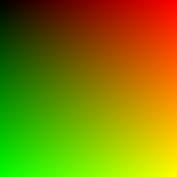


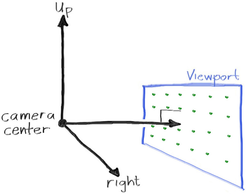
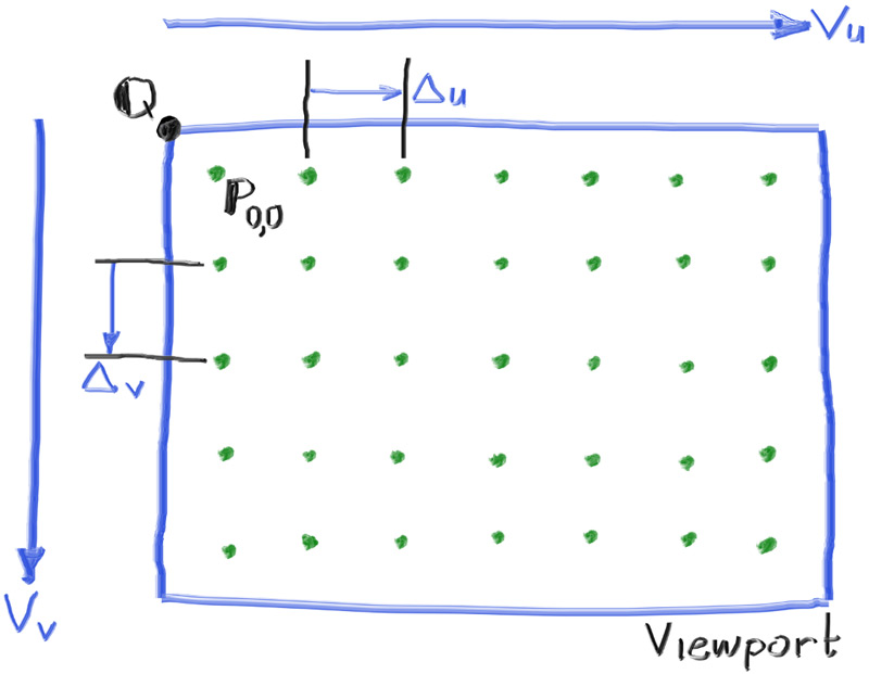

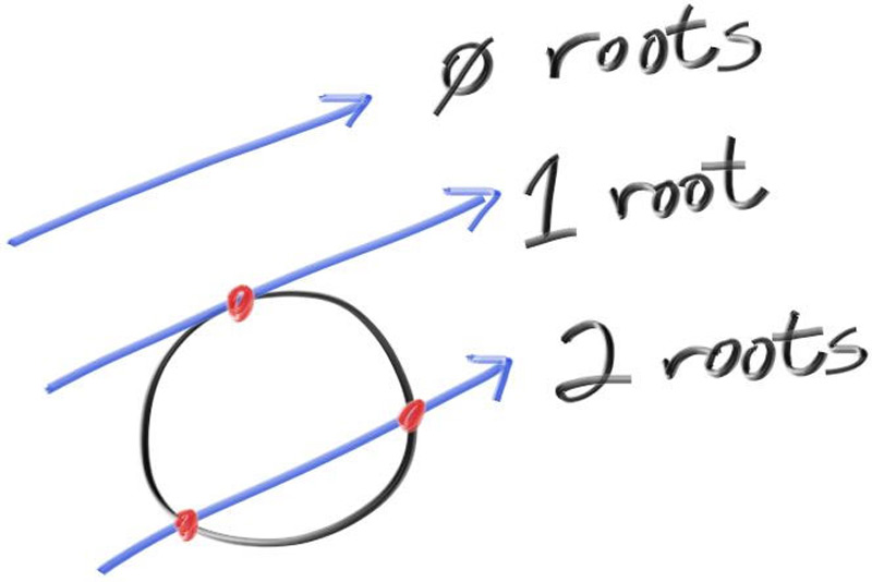
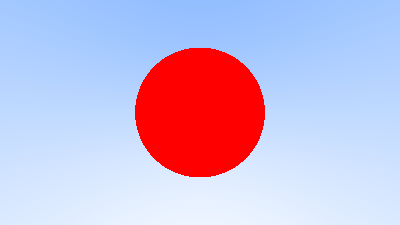
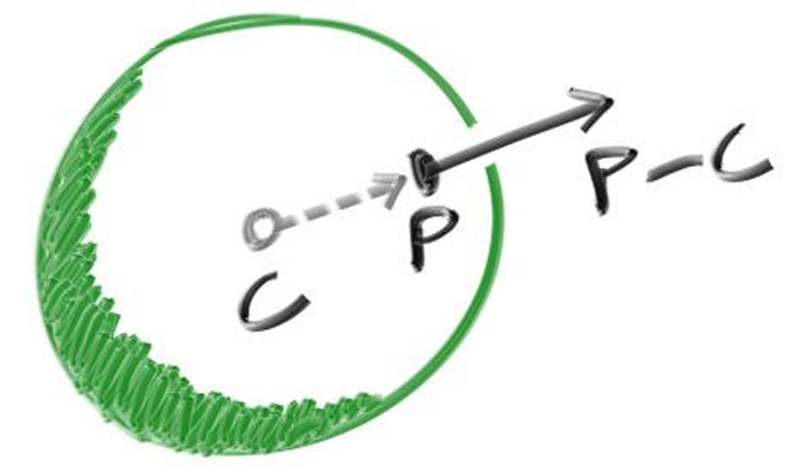
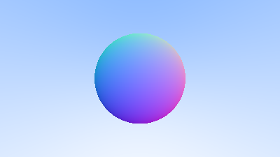
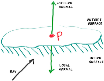
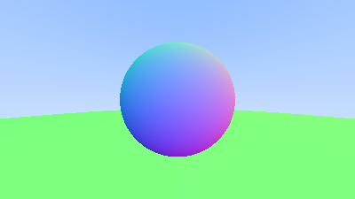
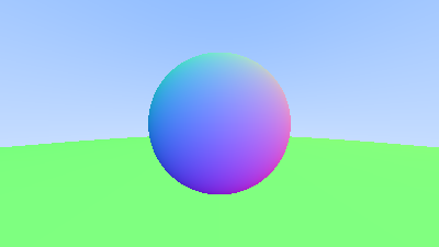


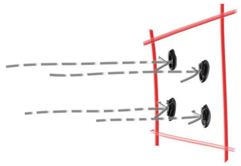

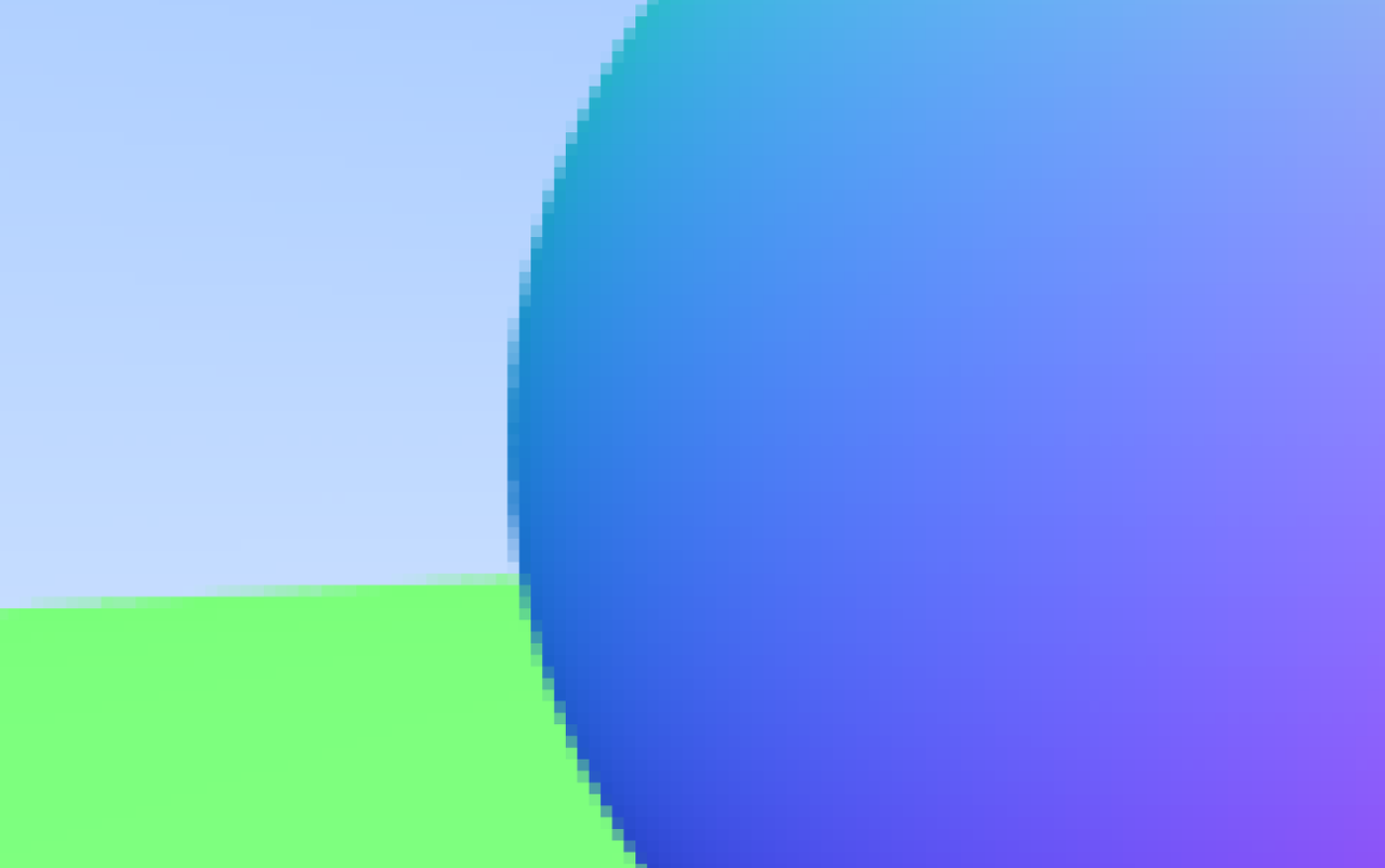
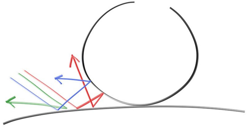
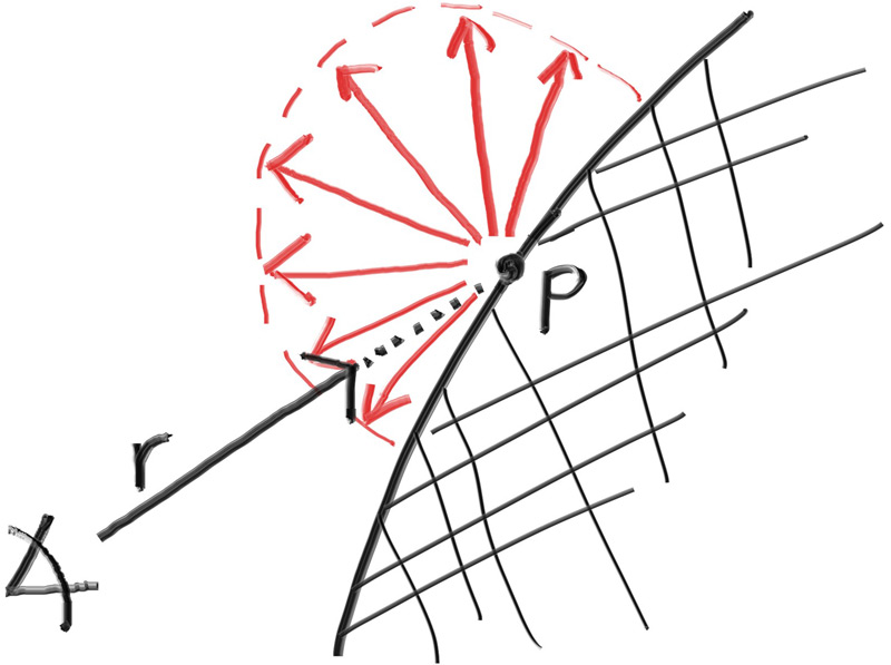
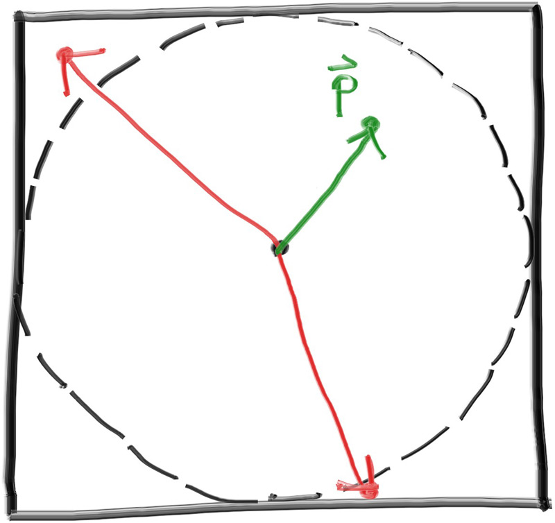
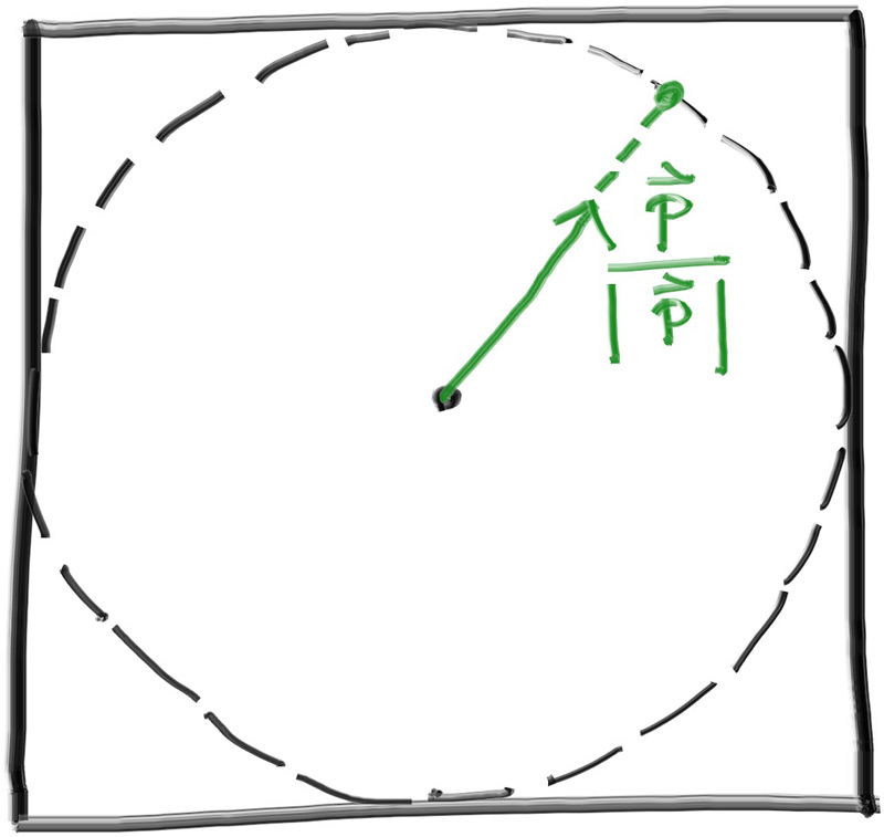
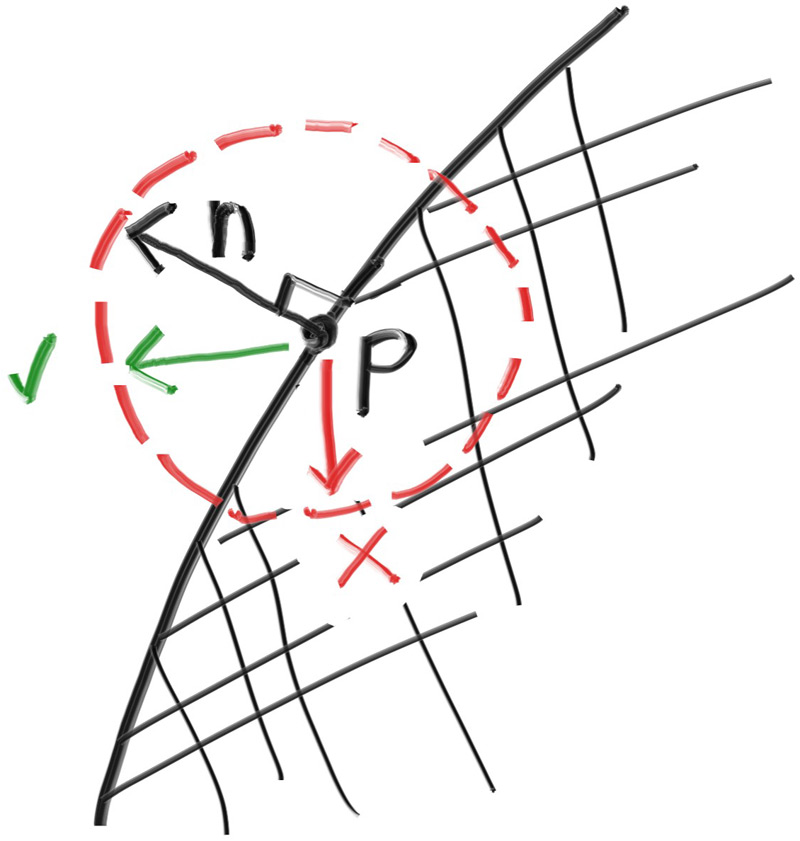
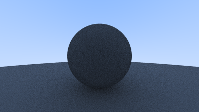
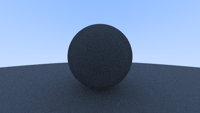
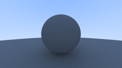
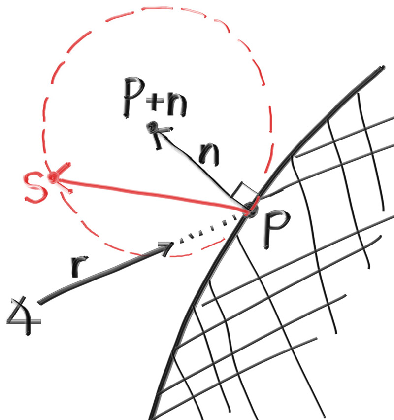
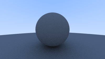
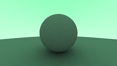
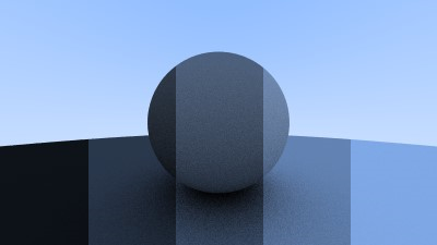
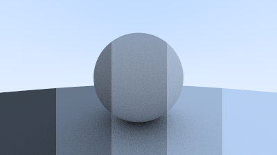
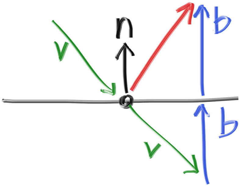
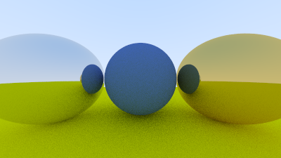
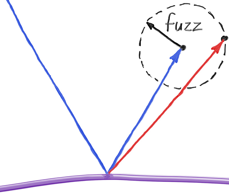
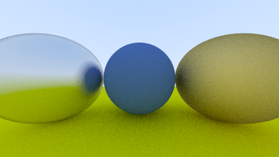
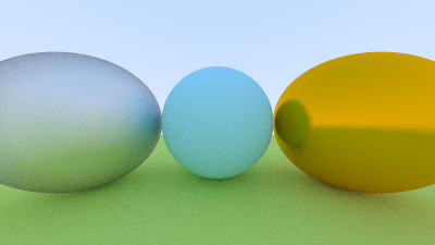
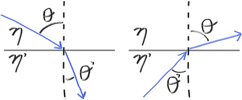
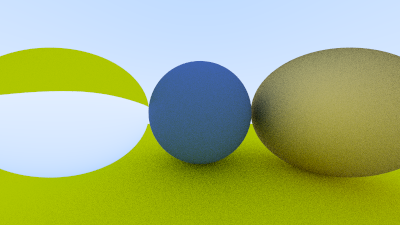
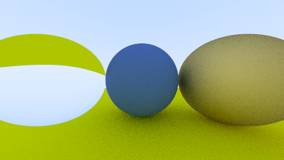
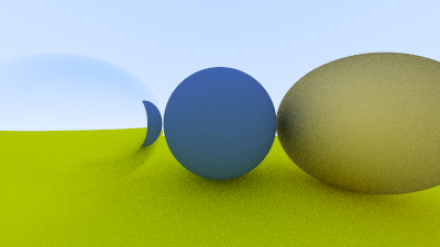
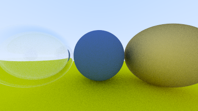
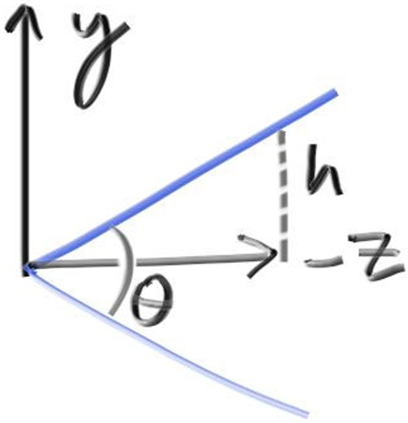
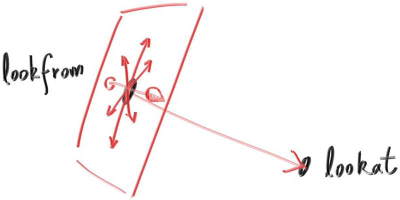

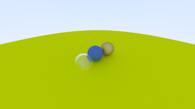
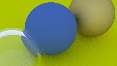
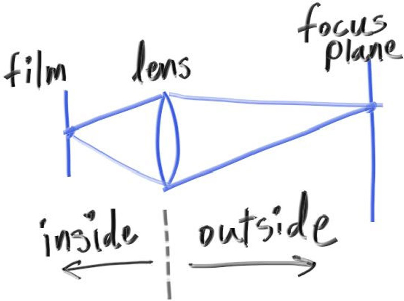
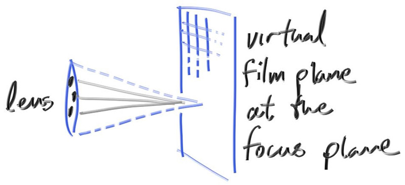
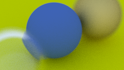
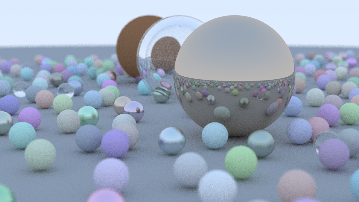
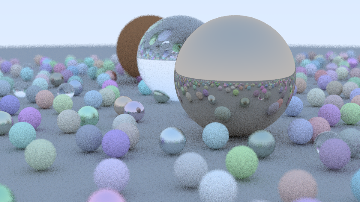
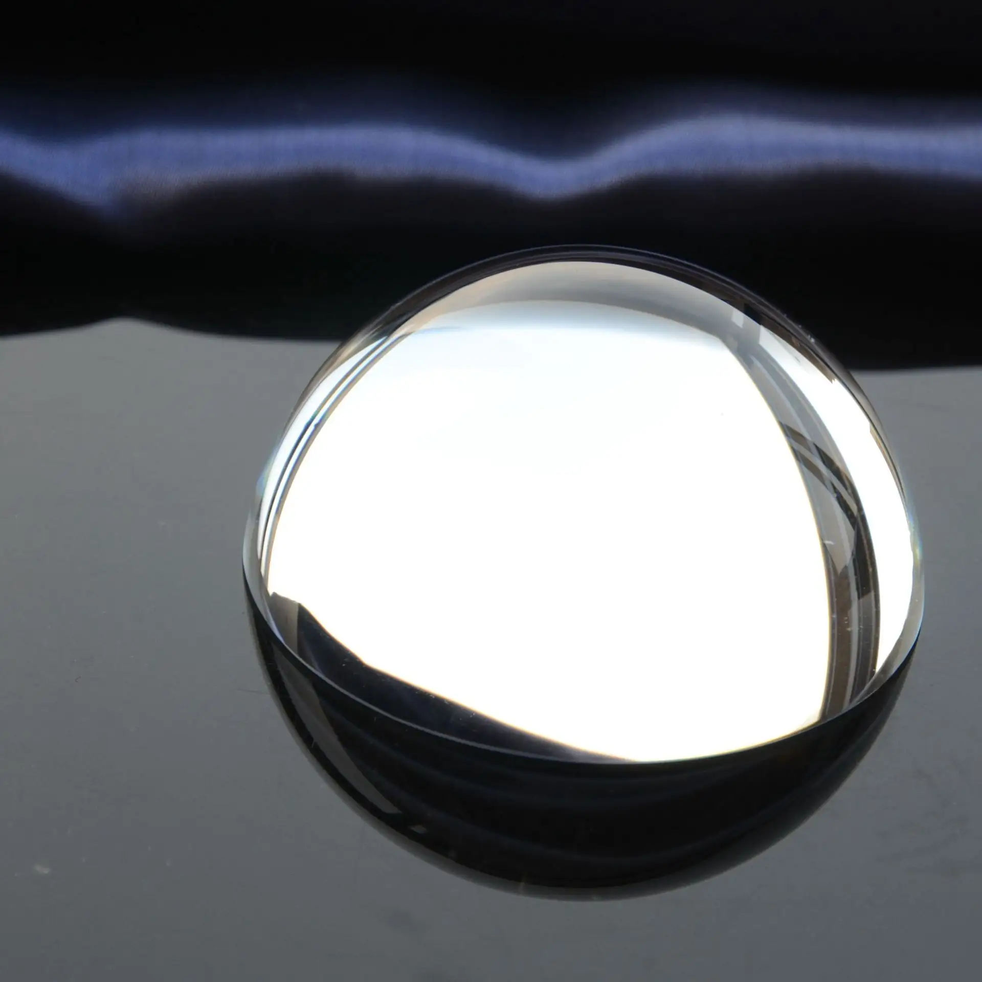

厉害啊,全部自己翻译的?
欢迎AT4佬 😭
@ZigZagK
感谢zzk收留